
Why integrate analysis and connection design
Industrial structures pose challenges that make manual connection design costly:
- Team coordination: many disciplines share large amounts of information and data.
- Congested joints: nodes with multiple members and tight spaces.
- High and unusual loads: equipment, piping, and tanks create many load combinations and torsion in members, since these structures often lack diaphragms.
- Hollow structural sections (HSS): they offer a high strength-to-weight ratio and good performance in compression and torsion, but their connections are complex to design.
An integrated workflow addresses these challenges by reusing data that is already modeled, avoiding manual input and associated errors, keeping data in a single central source, and designing intelligently by groups.
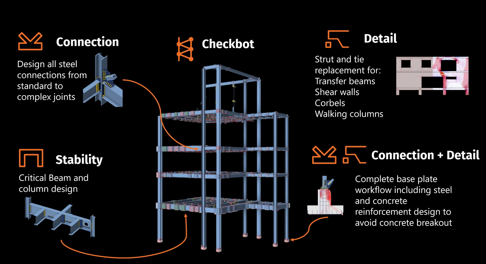
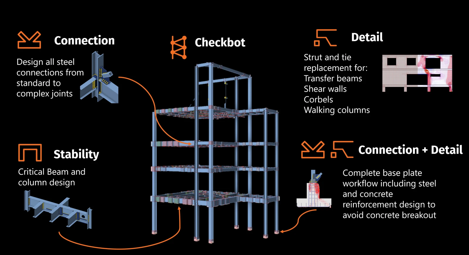
The IDEA StatiCa applications involved
- Checkbot is the integration hub. It imports analytical models from the leading analysis and BIM programs, manages hundreds of connections, and synchronizes design changes. The interface is the same regardless of the source program.
- Connection designs steel connections, from everyday shear and moment connections to complex, non-standard joints.
- Stability analyzes the critical portions of a member, taking into account the actual stiffness of the connected joints.
- Detail checks reinforced concrete regions where traditional methods struggle, such as transfer beams, shear walls, corbels, and discontinuity regions.
- Connection and Detail work together in cases such as base plates: the steel, the anchors, and the concrete reinforcement are checked in a single environment.
Example project and overall workflow
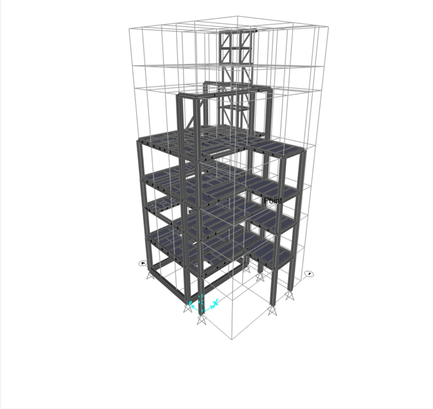
The example is an industrial plant structure that has already been analyzed and designed in SAP2000; our task is to design the connections and deliver the calculation package.
| Item | Value |
| Total weight | 94 t (metric tons) |
| Plan area | 13 m × 9 m |
| Highest point | 25 m |
| Sections | Wide-flange shapes, channels, and HSS |
The workflow follows six steps, detailed below:
- Structural analysis in SAP2000
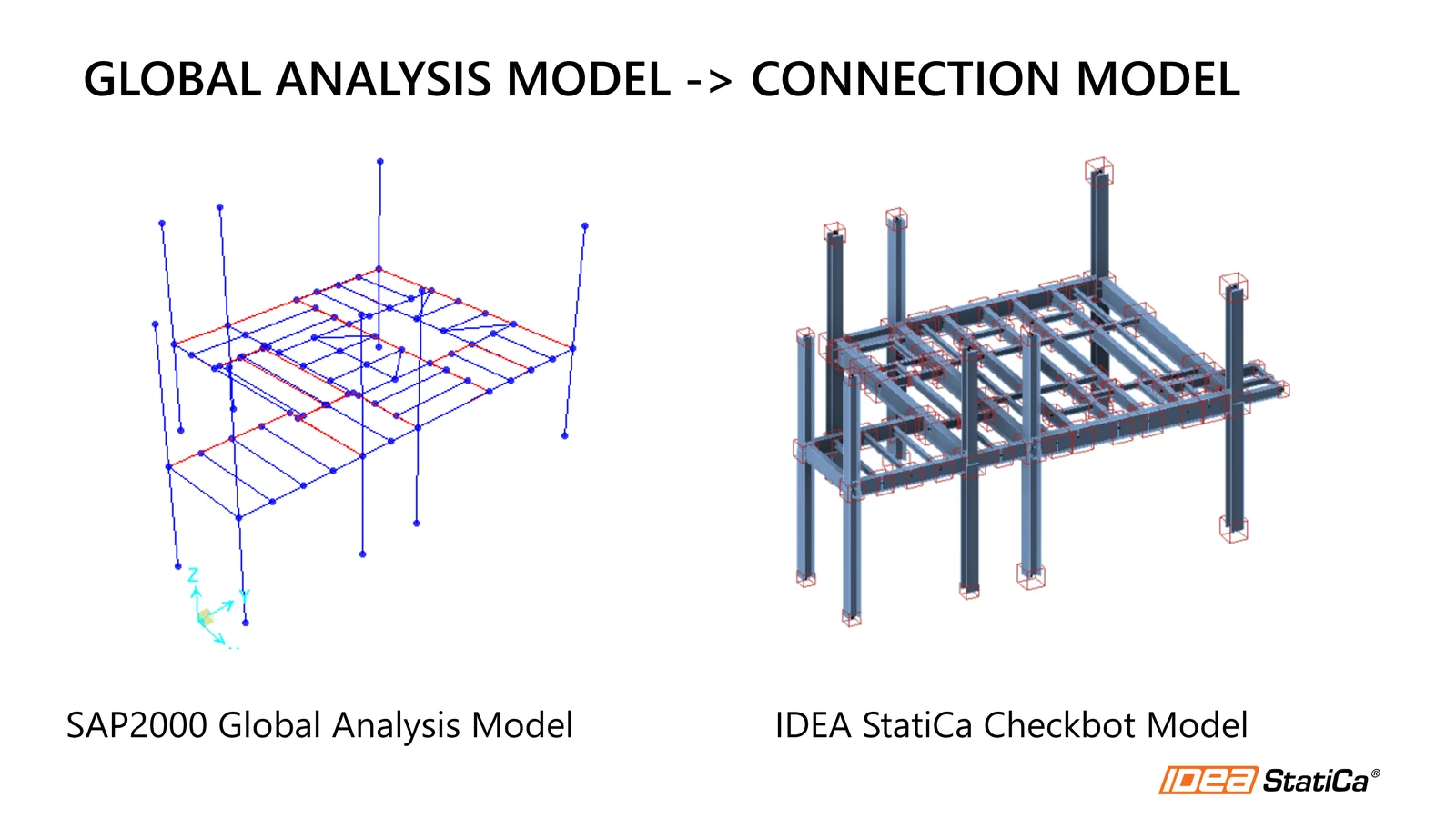
- Export the model to Checkbot
- Prepare the model
- Design connections by groups
- Design the foundation concrete (pedestal)
- Generate the calculation package
Step 1: Activate the link and start from the SAP2000 analysis
The starting point is the global analysis model in SAP2000, with the analysis already run: members, geometry, and deformed shape are available.
No programming is needed to connect SAP2000 to Checkbot: the link already exists and is easily added to SAP2000 as a plugin.
- Install the prerequisites listed on the IDEA StatiCa website, such as .NET.
- In SAP2000, add the plugin located in the IDEA StatiCa installation folder: Go to Tools> Add/Show Plugin>: Browse "C:\Program Files\IDEA StatiCa\StatiCa 26.1\net48\IdeaSAP2000v1PluginWrapper.dll"
- Confirm that the Checkbot plugin is available in SAP2000.
Step 2: Export the model to Checkbot
- With the analyzed model open in SAP2000, run the Checkbot plugin. Checkbot opens automatically.
- Select the design codes you want to follow.
- Select the members to import. In this example, all frame sections are selected; there is no need to import slabs or walls.
- Checkbot imports the geometry, nodes, and loads. Check that the model looks as expected; you can isolate a floor to inspect it.
Step 3: Prepare the model in Checkbot
A global analysis model is not always ready for connection design as is, so some post-processing is advisable.
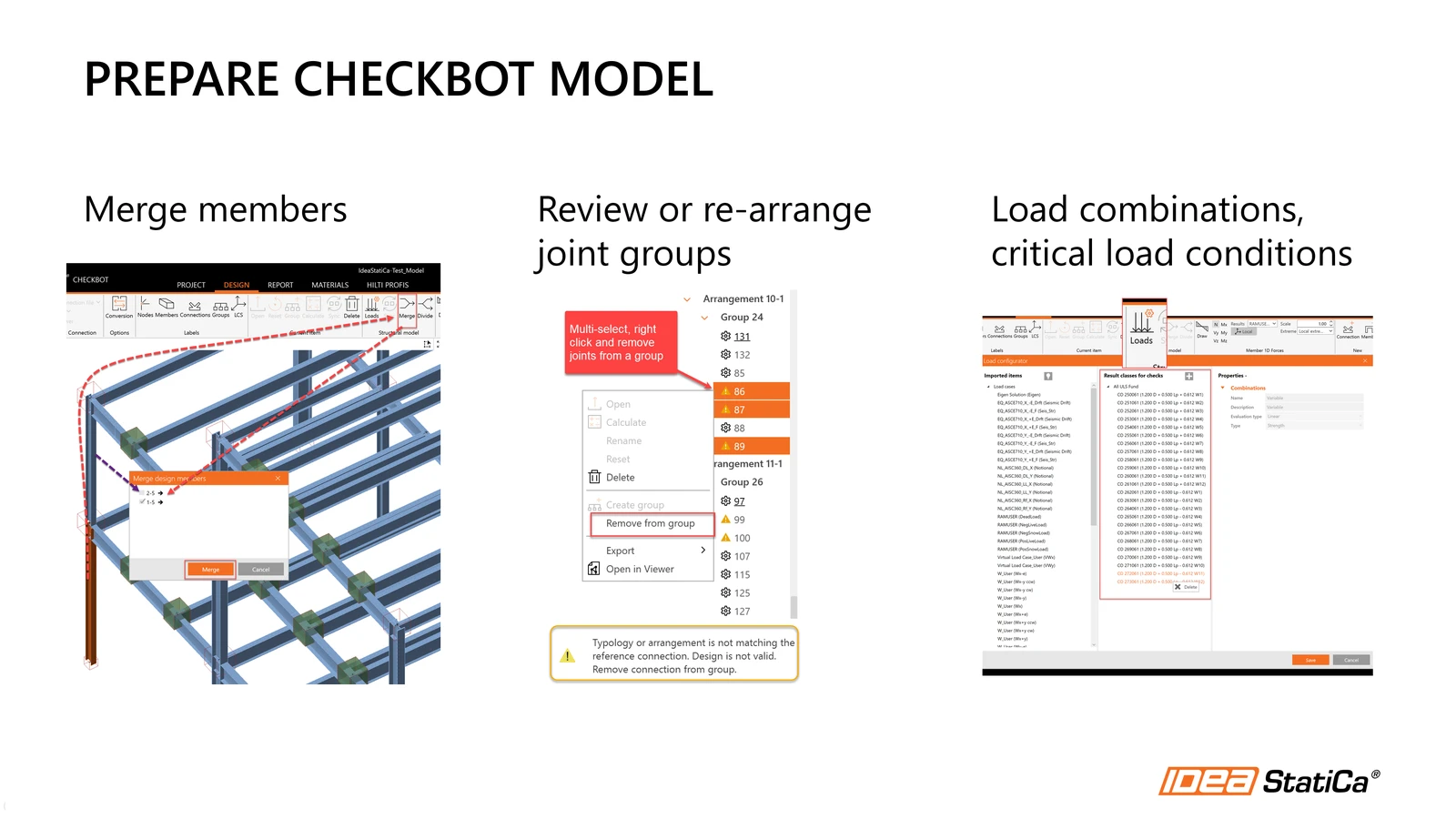
- Merge columns. In the global model, columns are broken at each floor. Use the Merge function to create continuous columns between the actual splice locations; Checkbot detects which columns can be merged based on their location and section.
- Align beams to top of steel. Choose the beam insertion point from the drop-down menu so the top-of-steel elevation is consistent, instead of the centerline alignment of the global model.
- Review the loads. Use the Member1D forces tool to check shears, moments, and axial forces and confirm that everything was imported correctly. Also review the load combinations and governing load cases.
- Reorganize the joint groups. Group assignment is automatic, but you can change it if the geometry has changed: select the members, right-click, and choose to remove them from the group.
Step 4: Design connections by groups
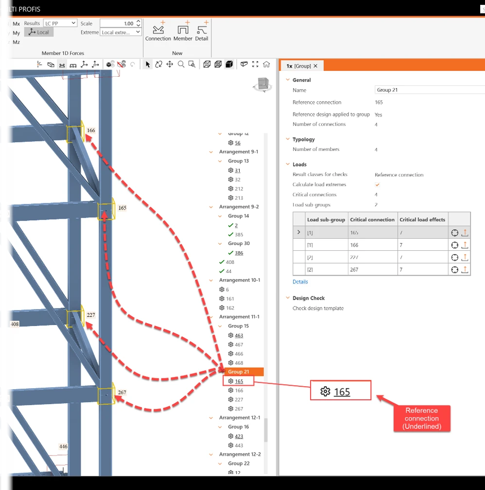
After the import, Checkbot applies dynamic grouping: it groups joints by typology (number of members and orientation) and then by arrangement (cross-sections). Each group is designed only once.
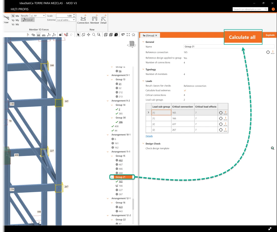
1. Identify the reference connection. Click a group's title to highlight its joints in the structure. The underlined joint in the list is the reference connection; there is only one per group, and it is the one you open and design.
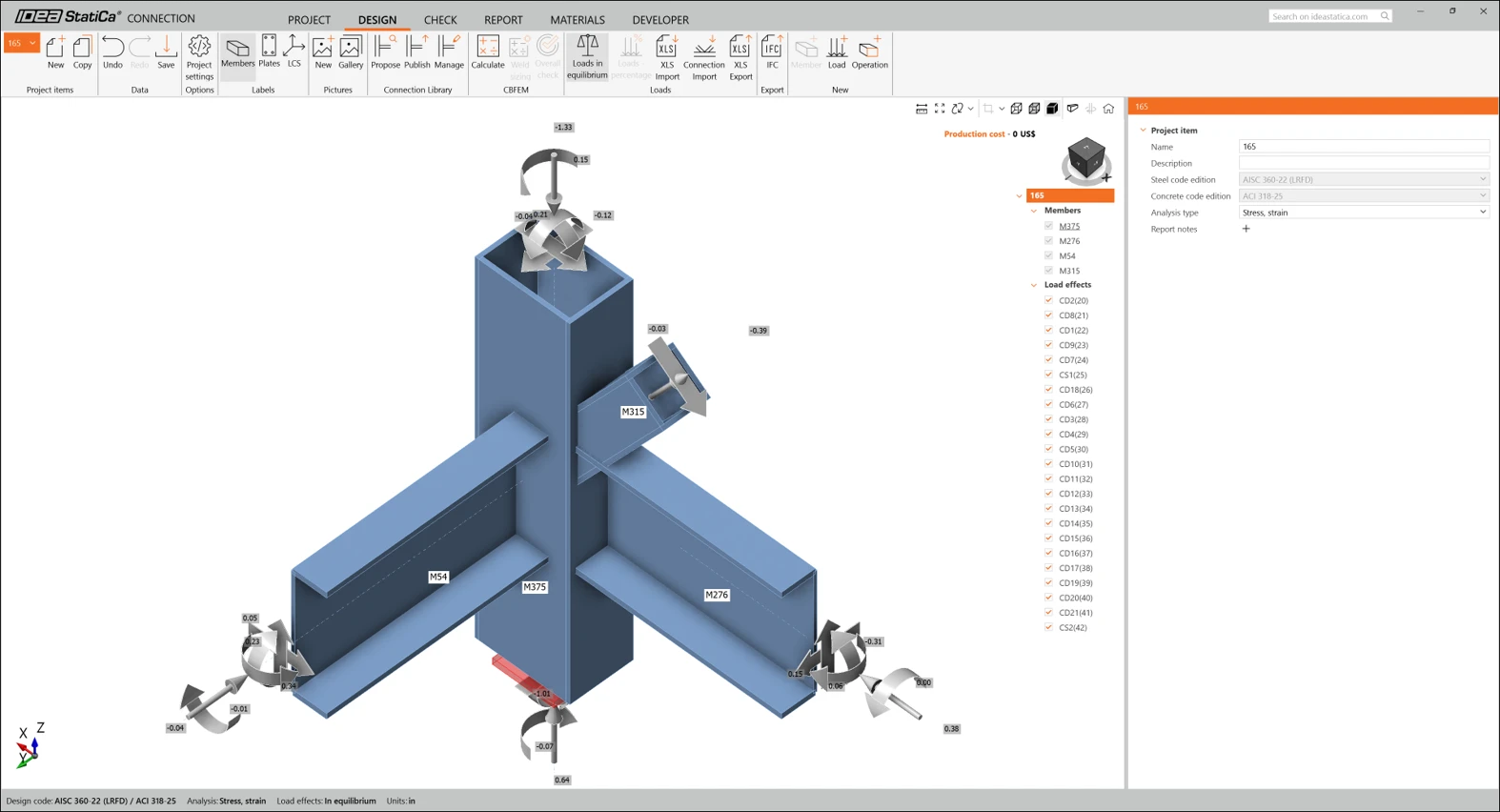
2. Open the reference connection in Connection. You will see the loads from the different combinations and the member geometry. The members are not yet connected: they must be cut to the correct length, and plates, bolts, and welds must be added.
3. Model the connection. There are two options:
- Manufacturing operations: bolts, welds, plate cuts, and standard connections. For example, a shear tab automatically adds bolts and welds and cuts the beam to length; plate thickness and weld size are adjusted in the properties window.
- Parametric design using templates.
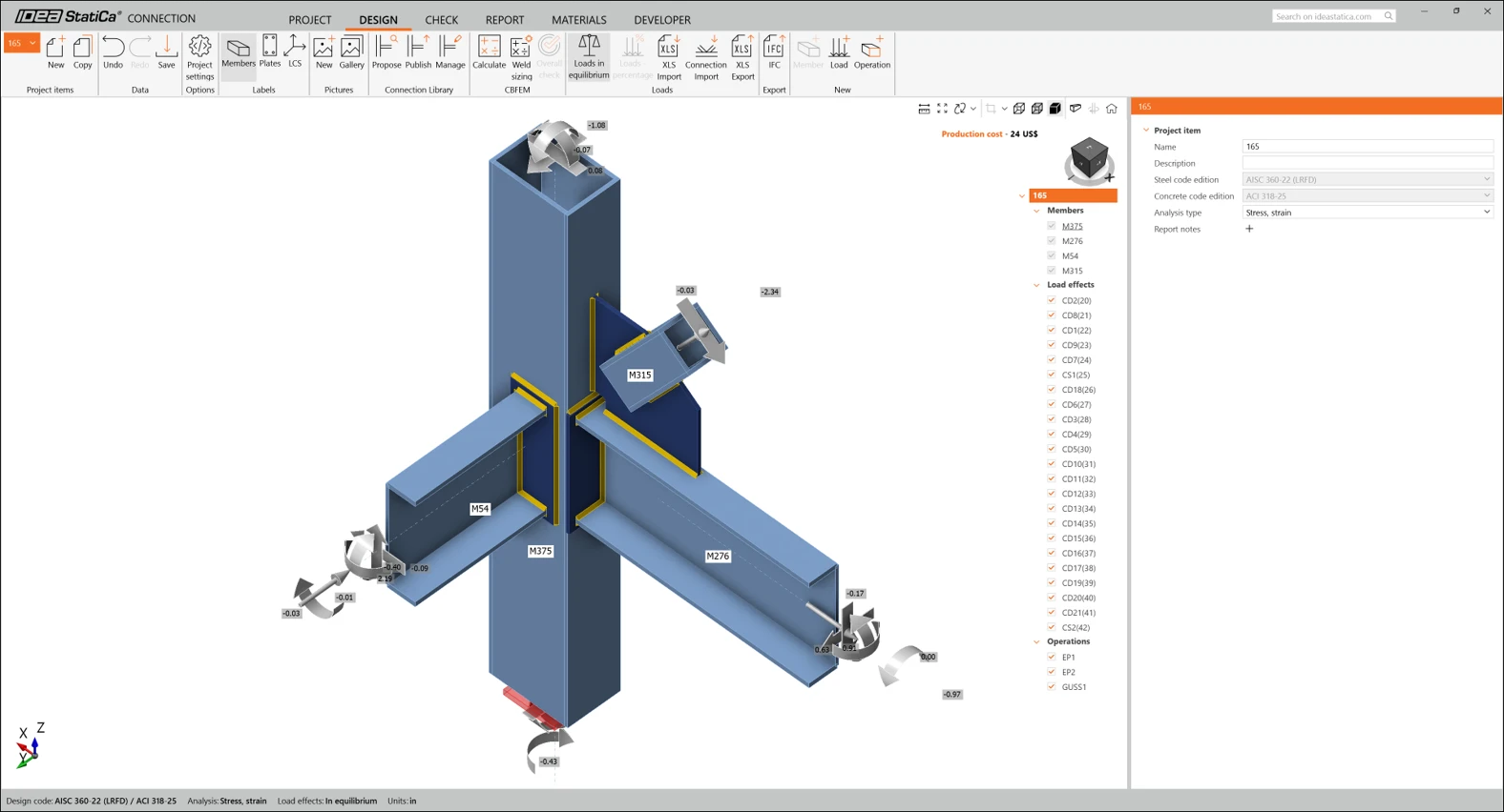
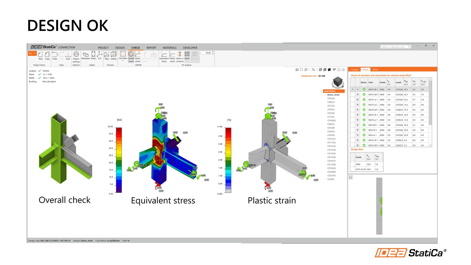
4. Check the design. Run the joint analysis and review the overall check, equivalent stresses, and plastic strain, along with the numerical results. Bolts and welds are checked according to the design code selected in Step 2.
5. Apply the design to the whole group. Close Connection, return to Checkbot, and run “Calculate all.” The reference connection design is copied to every joint in the group, and each one is checked with its own loads.
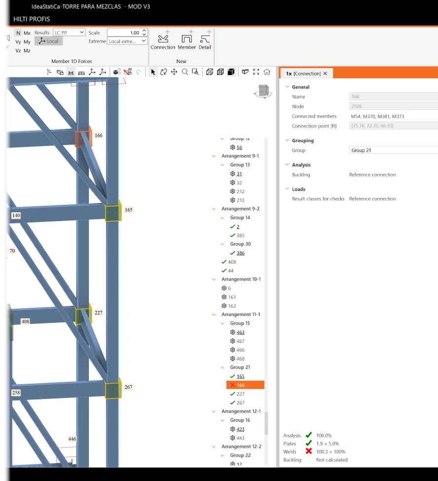
6. Review the summary. Checkbot shows the status of each joint and the results for plates, bolts, and welds.
Atypical connections that are not part of a group, such as column splices, end plates, haunches, or multi-member joints, are designed individually in Connection. In the example, the results were as follows:
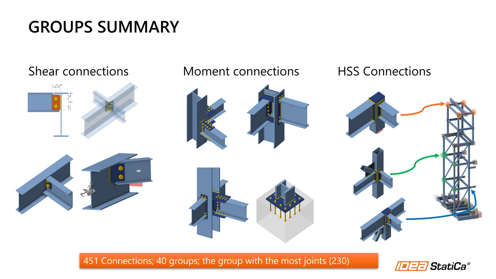
| Result | Value |
| Connections | 451 |
| Groups | 40 |
| Group with the most joints | 230 (beam-to-beam shear tab) |
| Base plates | 8 |
| Maximum members at one joint | 5 |
Step 5: Design the foundation concrete
Connection checks the base plate, welds, and anchors, but treats the concrete block as unreinforced. To check the pedestal reinforcement, use Detail.
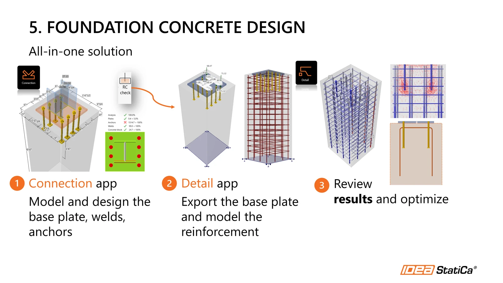
- In Connection, define the base plate: the steel plate, the anchors (cast-in-place or post-installed), and the concrete block.
- Review the results: tension and shear forces in the anchors and the code equation calculations. In the example, concrete breakout of the anchors does not pass without reinforcement.
- Export the base plate to Detail and model the pedestal reinforcing steel.
- Review the results in Detail and optimize the design.
Step 6: Generate the calculation package
Once all groups are designed, Checkbot generates the deliverables in a few minutes.
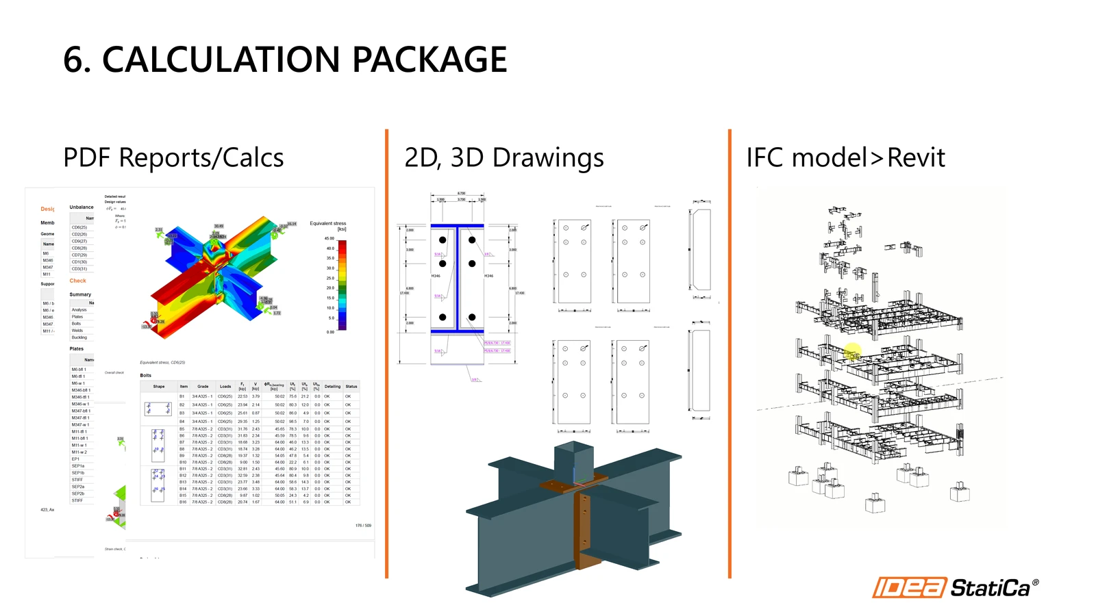
- PDF reports. Choose a brief or detailed report and include all connections or only some; you can get all reports in a single file. The detailed report includes members and forces, plates (shear tabs, flange plates, stiffeners), maximum stresses and strains, contour plots, and isometric views.
- 2D and 3D drawings of the connections.
- IFC model, which can be opened in BIM programs such as Revit.
- Links to the online viewer to share the models.
Results: time spent
The integrated workflow completed the project in about 16 hours (about 2 working days), compared with an estimated 78 hours (about 2 work weeks) using traditional methods. The integrated-workflow hours were logged during the exercise; the traditional hours are an IDEA StatiCa estimate.
| Process | Integrated workflow with IDEA StatiCa (h) | Traditional methods (h) |
| Connection design | 10 | 50 |
| Foundation design | 4 | 16 |
| Calculation package | 2 | 12 |
| Total | 16 h | 78 h |
The final deliverable included 451 connections designed in 40 groups, 8 base plates with pedestal reinforcement checks, PDF reports, 2D drawings, the IFC model, and links to the online viewer.
Conclusion and next steps
Integrating SAP2000 and IDEA StatiCa lets you reuse data from the original model, avoid manual input errors, keep a single source of truth, design by groups, and check every joint with the actual loads from all load combinations. Follow the step-by-step tutorials to model typical and atypical connections.