
The anchor bolt is modeled with similar procedures as the structural bolts. The bolt is fixed on one side of the concrete block. Its length, Lb, used for bolt stiffness calculation, is taken as a sum of half of the nut thickness, washer thickness, tw, base plate thickness, tbp, grout or gap thickness, tg, and free the length embedded in concrete which is expected as 8d where d is a bolt diameter. Factor 8 is editable in the Code setup. This value is in accordance with the Component Method (EN1993-1-8); the free length embedded in concrete can be modified in Code setup. The stiffness in tension is calculated as k = E As / Lb. The load-deformation diagram of the anchor bolt is shown in the following figure. The values according to ISO 898:2009 are summarized in the table and in the formulas below.
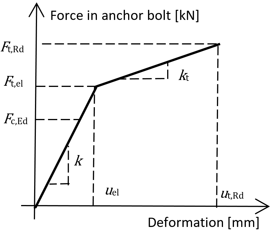
Load–deformation diagram of the anchor bolt
\[ F_{t,el}=\frac{F_{t,Rd}}{c_1 c_2 - c_1 + 1} \]
\[ k_t = c_1 k; \qquad c_1 = \frac{R_m - R_e}{\left ( \frac{1}{4} A - \frac{R_e}{E} \right )E} \]
\[ u_{el} = \frac{F_{t,el}}{k}; \qquad u_{t,Rd} = c_2 u_{el}; \qquad c_2 = \frac{AE}{4R_e} \]
where:
- A – elongation
- E – Young's modulus of elasticity
- Ft,Rd – steel tensile resistance of the anchor
- Rm – ultimate (tensile) strength
- Re – yield strength
The stiffness of the anchor bolt in shear is taken as the stiffness of the structural bolt in shear.
Anchor bolts with stand-off
Anchors with stand-off can be checked as a construction stage before the column base is grouted or as a permanent state. Anchor with stand-off is designed as a bar element loaded by shear force, bending moment, and compressive or tensile force. The anchor is fixed on both sides; one side is 0.5×d below the concrete level, the other side is in the middle of the thickness of the plate. The buckling length is conservatively assumed as twice the length of the bar element. Plastic section modulus is used. The forces in anchor with stand-off are determined using finite element analysis. The bending moment is dependent on the stiffness ratio of anchors and base plate.
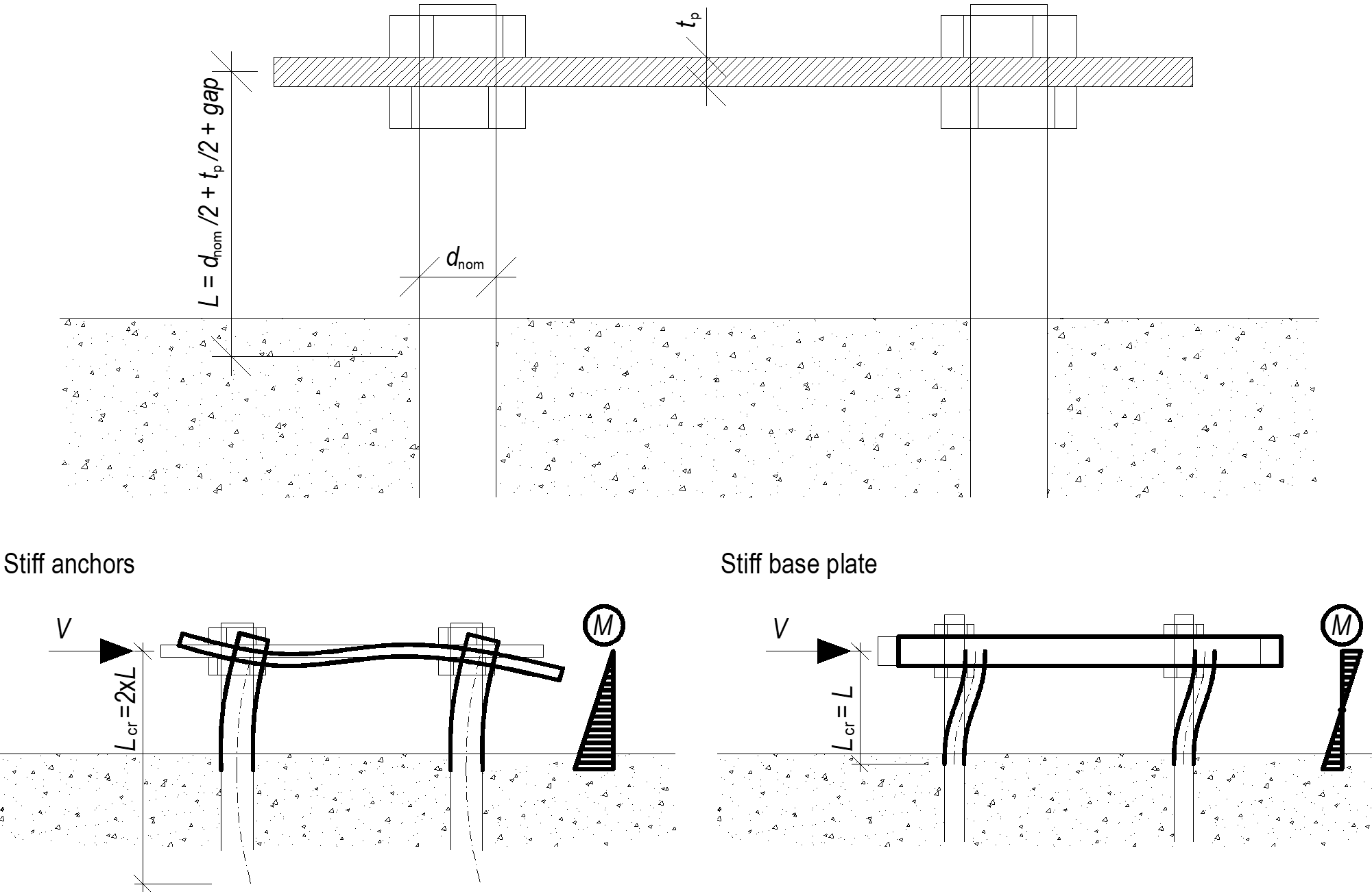
Anchors with stand-off – determination of lever arm and buckling lengths; stiff anchors are safe assumption