
Fillet welds are checked according to S16-14 - Chapter 13. The strength of CJP groove welds is assumed the same as the base metal and is not checked.
Fillet welds
The resistance for direct shear and tension or compression induced shear is designed according to S16-14 – 13.13.2.2. Plastic redistribution in weld material is applied in Finite Element Modelling.
\[ V_r = 0.67 \phi_w A_w X_u (1+0.5 \sin^{1.5} \theta ) M_w \]
where:
- ϕw = 0.67 – resistance factor for weld metal, editable in Code setup
- Aw – area of effective weld throat
- Xu – ultimate strength as rated by the electrode classification number
- θ – angle of axis of weld segment with respect to the line of action of applied force (e.g., 0° for a longitudinal weld and 90° for a transverse weld)
- \( M_w = \frac{0.85+\theta_1 / 600}{0.85+\theta_2 / 600} \) – strength reduction factor for multi-orientation fillet welds; equals to 1.0 in IDEA and the resistance of multi-orientation welds is determined by FEA where the most stressed element is assessed
- θ1 – orientation of the weld segment under consideration
- θ2 – orientation of the weld segment in the joint that is nearest to 90°
Base metal capacity at the fusion face:
\[ V_r = 0.67 \phi_w A_m F_u \]
where:
- Am = z L – area of the fusion face
- z – leg size of the weld
- L – length of the weld
- Fu – specified tensile strength
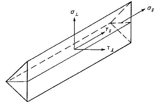
The weld diagrams show stress according to the following formulas:
If base metal is deactivated (matching electrode is used):
\[ \sigma = \frac{\sqrt{ \sigma_{\perp}^2 + \tau_{\perp}^2 + \tau_{\parallel}^2 }}{1+0.5 \sin^{1.5}{\theta}} \]
If base metal is activated (matching electrode is not used):
\[ \sigma = \max \left \{ \frac{\sqrt{ \sigma_{\perp}^2 + \tau_{\perp}^2 + \tau_{\parallel}^2 }}{1+0.5 \sin^{1.5}{\theta}}, \, \frac{\sqrt{ \sigma_{\perp}^2 + \tau_{\perp}^2 + \tau_{\parallel}^2 }}{\sqrt{2} F_u / X_u} \right \} \]
CJP groove welds
The resistance of Complete Joint Penetration (CJP) groove welds is assumed as that of the base metal.