Idea Statica
  • Steel
  • Concrete
  • BIM & workflows
  • Support & Learning
  • Pricing
  • Company
  • Steel overview
  • Connection design
  • Member design
  • Parametric design
  • Steel case studies
  • Concrete overview
  • Walls and D-regions
  • Anchoring design
  • Members & cross-sections
  • Concrete case studies
  • BIM overview
  • Supported integrations
  • Checkbot
  • Viewer
  • APIs
  • Support Center
  • E-learning & certification
  • Blog
  • Downloads & Licensing
  • Plans
  • Free community tool
  • Enterprise customers
  • Students & educators
  • How much will you save?
  • About us
  • Contact
  • Research & development
  • Authorized resellers
  • Meet our customers
  • Career
  • Steel
    Steel overviewConnection designMember designParametric designSteel case studies
  • Concrete
    Concrete overviewWalls and D-regionsAnchoring designMembers & cross-sectionsConcrete case studies
  • BIM & workflows
    BIM overviewSupported integrationsCheckbotViewerAPIs
  • Support & Learning
    Support CenterE-learning & certificationBlogDownloads & Licensing
  • Pricing
    PlansFree community toolEnterprise customersStudents & educatorsHow much will you save?
  • Company
    About usContactResearch & developmentAuthorized resellersMeet our customersCareer
14-Day Trial
14-Day Trial
  • Steel
  • Concrete
  • BIM & workflows
  • Support & Learning
  • Pricing
  • Company

Subscribe to our newsletter

Company

  • About us
  • Partners
  • Careers
  • Patent

Resources

  • Customer projects
  • Case studies
  • Connection Library
  • Verification books

Legal

  • EULA
  • Global privacy policy
  • California Privacy
  • TOS Viewer
  • Licensing

Help

  • Contact
  • Quote request
  • Resellers
  • Downloads
FacebookInstagramLinkedInYouTube

© IDEA StatiCa 2009-2026

Trusted and used worldwide by engineers, fabricators & consultants.

Support CenterKnowledge Base ArticlesCode-check of concrete block according to Australian standards
Advanced analysis types for your steel structures
Concrete cone area of single anchor and group of anchors
Effective area in check of contact stress in concrete
EN anchoring code-check improvement
Limitations to checks of anchors
Anchorage formulas, tooltips
Calculation of anchors with stand-off
Hooked anchors/L-bolts in AISC
Import of anchoring from Connection to Detail
Anchor bolts
Structural model of a concrete block
Code-check of anchors according to Australian standards
Check of anchor tension as a bolt tension option (AS)
Code-check of concrete block according to Australian standards
Russian Standard (SP) anchorage
Code-check of anchors according to Chinese standard
Code-check of concrete block according to Chinese standard
Code-check of concrete block according to Hong Kong Code
Code-check of concrete block according to Indian standards
Code-check of concrete block according to Russian standards
Check of concrete block according to SP - new
The concrete below the base plate is simulated by Winkler subsoil with uniform stiffness, which provides the contact stresses. IDEA StatiCa - concrete design software for structural code-check of concrete constructions.
Connection designSteelKnowledge baseAS (Australia)Connection

Code-check of concrete block according to Australian standards

This article is also available in
ENCZDEESFRITPTNLHUROKRPLTHTRVIZH

Concrete below base plate is simulated by Winkler subsoil with uniform stiffness, which provides the contact stresses. The average stress at the loaded area in contact with base plate is used for compressive check.

Concrete bearing surface

Concrete bearing surface is checked according to AS3600: 2018 – Cl. 12.6. The design bearing stress at a concrete surface shall not exceed:

ϕfb=ϕ0.9fc′A2A1≤ϕ1.8fc′ϕ f_b = ϕ 0.9 f'_c \sqrt{\frac{A_2}{A_1}} \le ϕ 1.8 f'_cϕfb​=ϕ0.9fc′​A1​A2​​​≤ϕ1.8fc′​

where:

  • ϕ = 0.6 – capacity factor (Table 2.2) editable in Code setup
  • f'c – characteristic compressive cylinder strength of concrete at 28 days
  • A1 – bearing area
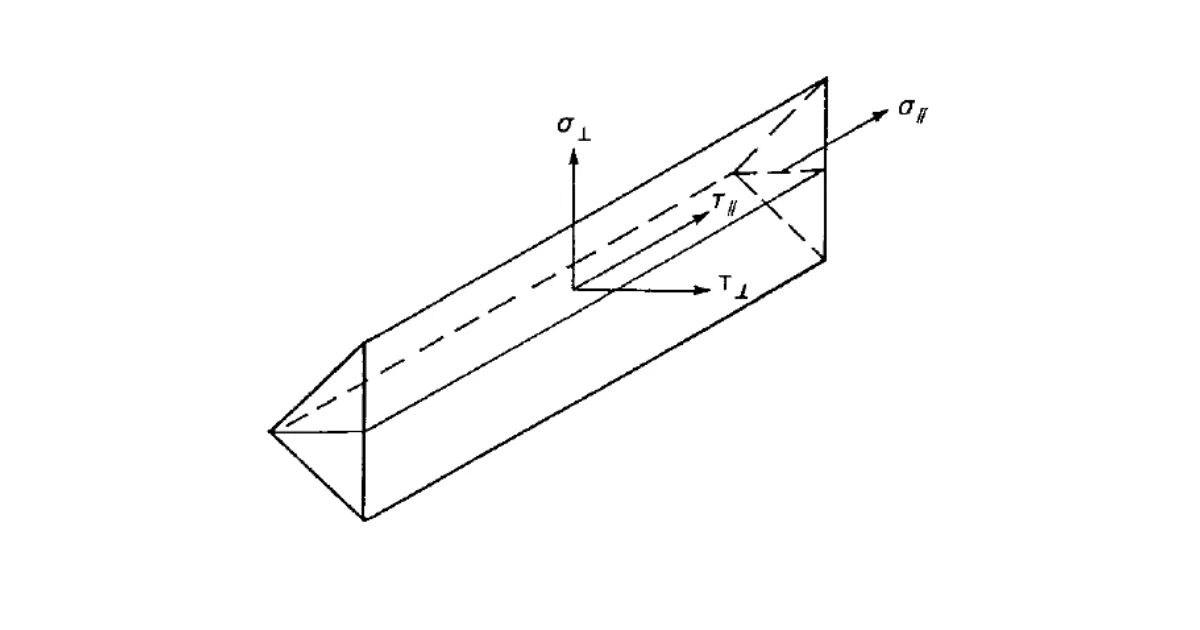
  • A2 – largest area of the supporting surface that is geometrically similar and concentric with A1. The side slopes of the frustum are 1 longitudinally and 2 transversally with respect to the direction of the load.

The design bearing stress, σ, equals to the average stress under the base plate on the area below the base plate in contact with concrete.

Transfer of shear

The shear action at the base plate is assumed to be transferred from the column to the concrete foundation by:

  1. Friction between base plate and concrete / grout
  2. Shear lug
  3. Anchor bolts

Shear force transfer by friction

The shear capacity is calculated according to Gianluca Ranzi, Peter Kneen: Design of Pinned Column Base Plates, Journal of the Australian Steel Institute, vol. 36, no. 2, September 2002 – Chapter 6.5.3 as follows:

ϕVf=ϕμNc∗ϕ V_f = ϕ μ N_c^*ϕVf​=ϕμNc∗​

where:

  • ϕ = 0.8 – capacity factor
  • μ = 0.55 – coefficient of friction editable in Code setup
  • Nc* – column design axial compression load

Shear force transfer by shear lug

If shear force is transferred by the shear lug, the shear lug is modeled by finite elements, and its plates and welds are checked by the finite element method and weld components. Additional checks are required – bearing concrete strength; concrete edge strength.

Bearing concrete strength

The bearing strength of concrete is checked according to Gianluca Ranzi, Peter Kneen: Design of Pinned Column Base Plates, Journal of the Australian Steel Institute, vol. 36, no. 2, September 2002 – Chapter 6.5.5:

ϕcVb=0.85ϕcfc′Aslϕ_c V_b = 0.85 ϕ_c f'_c A_{sl}ϕc​Vb​=0.85ϕc​fc′​Asl​

where:

  • ϕc = 0.6 – capacity factor for concrete in bearing editable in Code setup
  • f'c – characteristic compressive cylinder strength of concrete at 28 days
  • Asl – projected area of the embedded shear lug in the direction of the force, excluding the portion of the lug in contact with the grout above the concrete member

Concrete edge strength

If a shear force is acting against a free concrete edge it should be verified that the concrete is able to carry the applied shear action. The concrete edge strength is checked according to Gianluca Ranzi, Peter Kneen: Design of Pinned Column Base Plates, Journal of the Australian Steel Institute, vol. 36, no. 2, September 2002 – Chapter 6.5.5:

ϕVce=ϕ0.33fc′AVcϕ V_{ce} = ϕ 0.33 \sqrt{f'_c} A_{Vc}ϕVce​=ϕ0.33fc′​​AVc​

where:

  • ϕ =0.85 – capacity factor
  • f'c – characteristic compressive cylinder strength of concrete at 28 days
  • AVc – effective stress area defined by projecting a 45° plane from the bearing edges of the shear lug to the free surface in the direction of the shear load. The bearing area of the shear lug is excluded from the projected area

Shear force transfer by anchors

The shear force is assumed to be transferred by anchors. Force in each anchor is determined by finite element method. Each anchor or anchor group is checked for steel failure in shear, concrete edge failure, concrete pry-out failure, and combined tension and shear loading if tension is also present.
Related articles

Fillet welds are checked according to AS 4100 - Chapter 9.7. The strength of CJP groove welds is assumed the same as the base metal and is not checked. Structural design of welded steel connections and steel beam-to-column connections.
  • Steel
  • Connection
  • CBFEM
  • Welds
  • AS (Australia)
  • +5
  • Steel
  • Connection
  • CBFEM
  • Welds
  • AS (Australia)

Knowledge base

Code-check of welds according to Australian standards

Read more
Structural design and code-check of anchors according to Australian standards. The forces in anchors including prying forces are determined by finite element analysis, but the resistances are checked using code provisions of AS 5216.
  • Steel
  • Connection
  • Anchoring
  • CBFEM
  • Concrete block
  • Steel-to-concrete
  • AS (Australia)
  • +7
  • Steel
  • Connection
  • Anchoring
  • CBFEM
  • Concrete block
  • Steel-to-concrete
  • AS (Australia)

Knowledge base

Code-check of anchors according to Australian standards

Read more
General anchoring shapes and options
  • Steel
  • Connection
  • Geometry
  • Anchoring
  • Concrete block
  • Plates
  • Steel-to-concrete
  • Hilti
  • +8
  • Steel
  • Connection
  • Geometry
  • Anchoring
  • Concrete block
  • Plates
  • Steel-to-concrete
  • Hilti

Knowledge base

General anchoring shapes and options

Read more