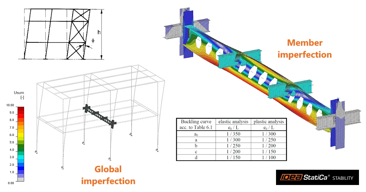


Buckling is rarely a property of an isolated member. It depends on the stiffness of the surrounding structure, the boundary conditions, the load position, imperfections, and – importantly – the actual behavior of the connections.
The Stability app brings all these parts together. Engineers can model the relevant part of the structure, verify the static system, design and check the connections, identify critical buckling shapes, introduce imperfections, and perform geometrically and materially nonlinear analysis with imperfections (GMNIA) – all within one connected workflow.
Instead of estimating the buckling length for an isolated member, the engineer can analyze how the member actually will buckle as part of the structure.
The solution reflects these main tasks:
- Check a steel member where buckling decides the design.
- Design and check the connections of that member as part of the same job.
- Check the members and substructures for stability resistance.
- Generate a single report covering the structure and its connections.
Quick navigation:
Model the structure around the analyzed member (members)
A reliable stability analysis starts with the right structural model.
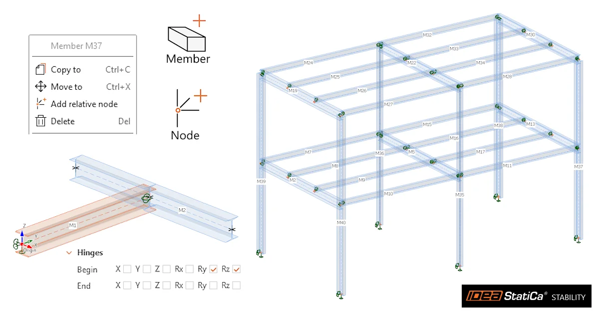
- In Stability, the engineer works with a substructure rather than an isolated member. Members, nodes, supports, hinges, eccentricities, loads, and combinations are defined directly in the 3D scene and remain editable throughout the design process.
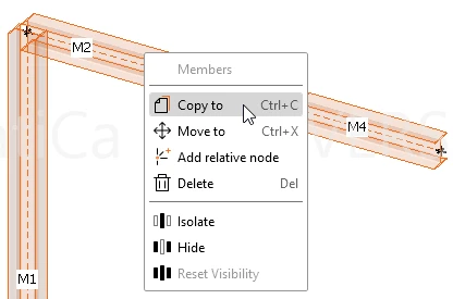
- Projects can start from a blank model, a prepared template, or an import from an FEA tool. Members can be added, removed, split, or repositioned without rebuilding the whole project.
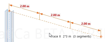
- Tracing and ortho guidance make it possible to create structural geometry directly in the scene. Repeated distances can be entered using a multiplier.
- Coincidentally doubled nodes are automatically merged to keep the structural model connected.
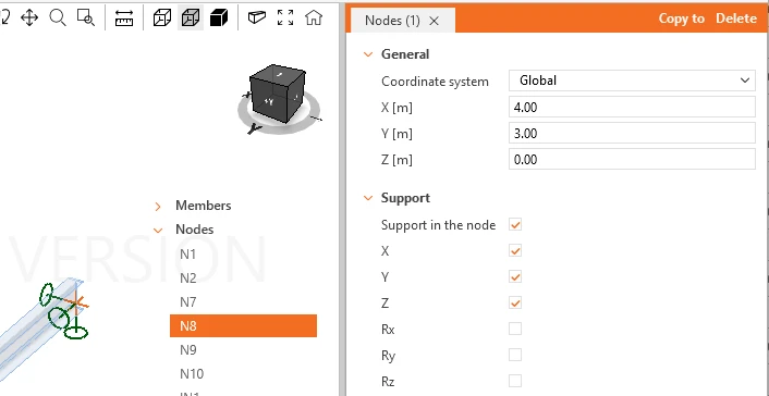
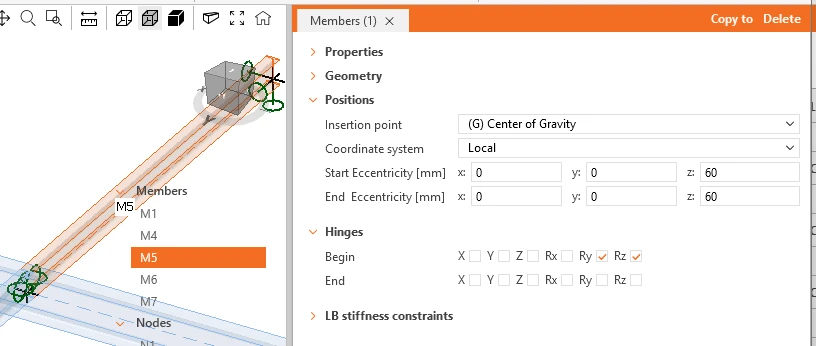
Supports and member-end hinges are visible directly in the scene, with their individual degrees of freedom available for editing. The model can therefore be inspected before any advanced stability analysis is performed.
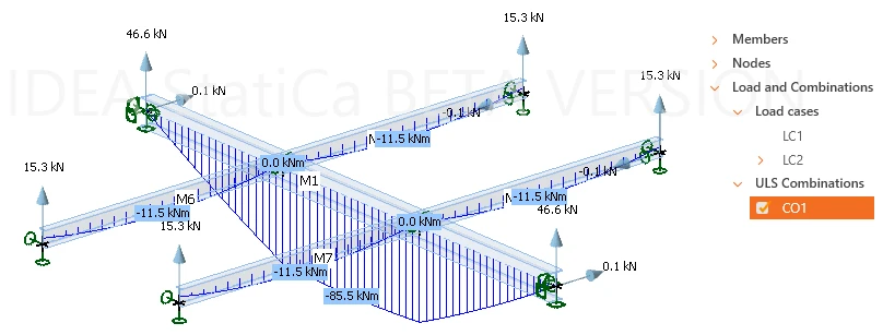
A linear analysis provides reactions, internal forces, and deformations, allowing the engineer to compare the structural response with engineering expectations before moving further in the workflow.
This gives the engineer a way to verify that the static system being analyzed is the one they intended to create.
Find out more about how to create a structural model in the Stability app in this article.
Loads as they exist in the structural model
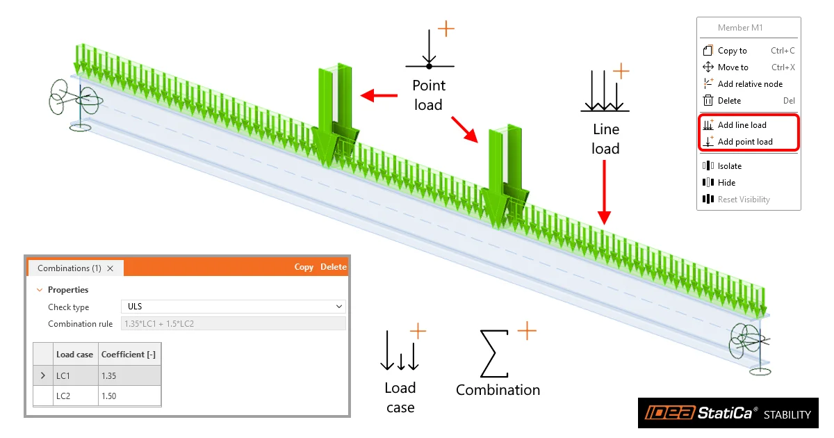
Stability works with load cases and load combinations, including automatic self-weight. Combinations are defined as ULS or SLS.
The user selects from Point and Line loads to be applied to the members.
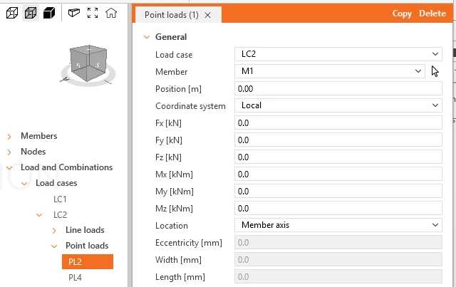
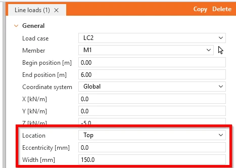
For shell-based members, the position of a load matters. A load can therefore act on the member axis or on one of its faces, including eccentricity and loaded width.
The same principle applies to member geometry. Start and end eccentricities can be defined independently, making it possible to represent members whose physical alignment changes between their ends.
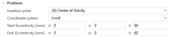
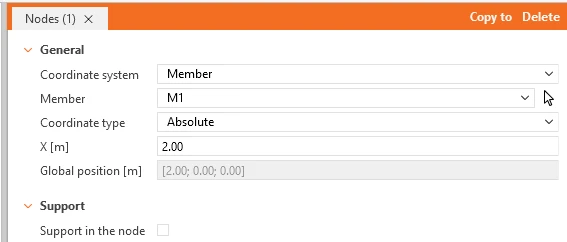
The result is a structural model that can first be checked using familiar linear-analysis results and then used consistently for the more advanced analyses that follow.
Learn how to define loads in the Stability step-by-step in this article.
Turn the critical member into a CBFEM model
Not every member of the substructure needs a detailed finite-element model.
Stability maintains the surrounding structure as 1D members while allowing the engineer to select the critical part and convert it into a CBFEM member modeled with shell finite elements.
CBFEM part of the model can consist of one or several members, and this selection remains editable. The rest of the modeled structure remains as 1D members, with only stubs needed for connection design. This provides detail where it matters while keeping the rest of the structural system simple.
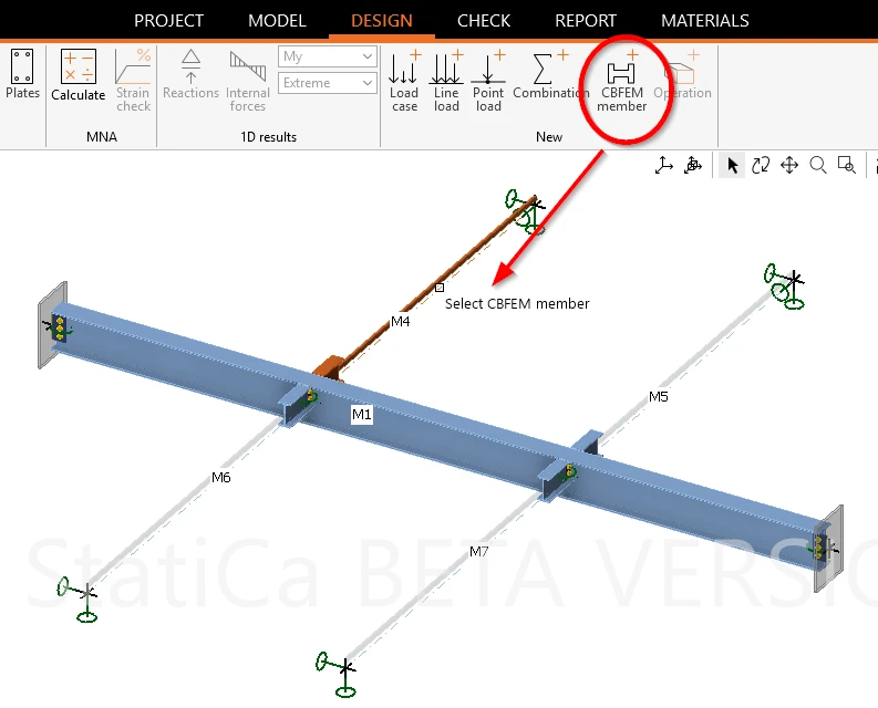
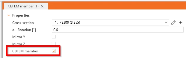
Find more information about defining Stability CBFEM members in this article.
Real connections become part of the stability model
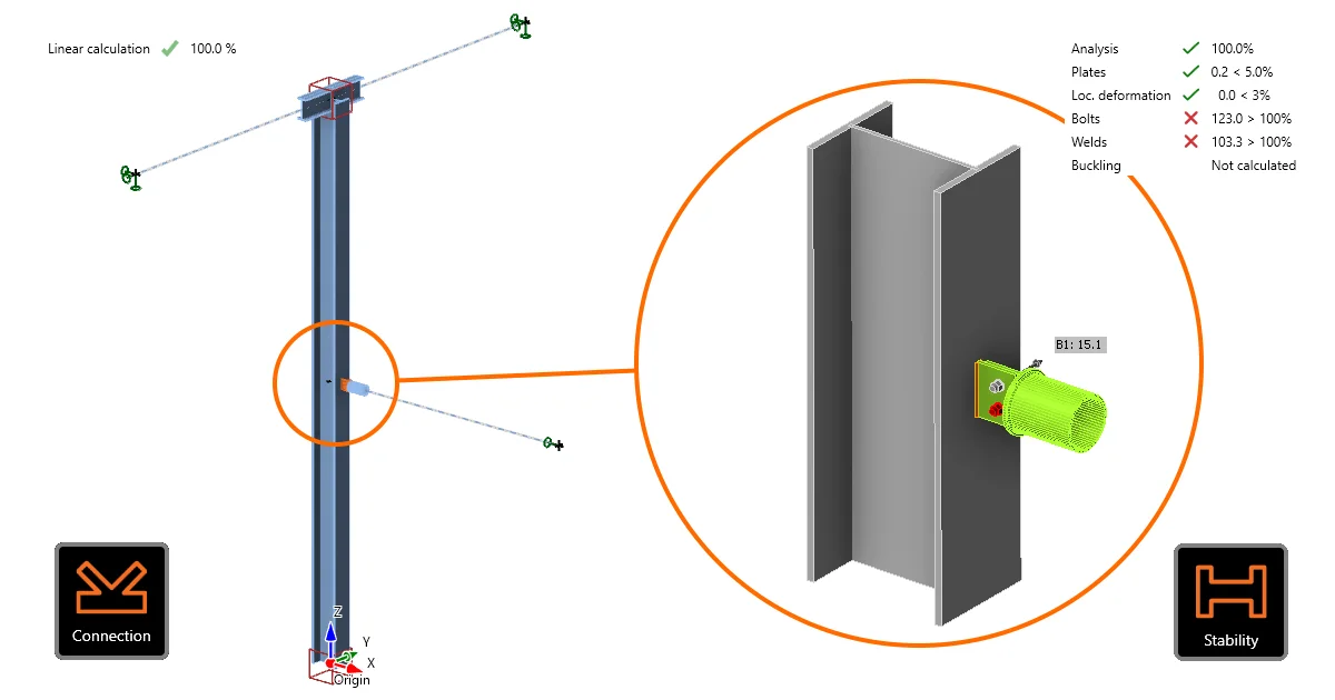
Creating a CBFEM member automatically identifies its nodes as connections.
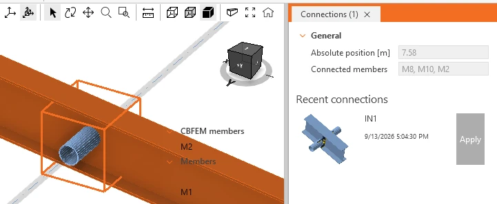
In a standalone Stability project, these connections can be opened directly in IDEA StatiCa Connection and designed using the familiar operations for plates, bolts, welds, stiffeners, and other connection components.
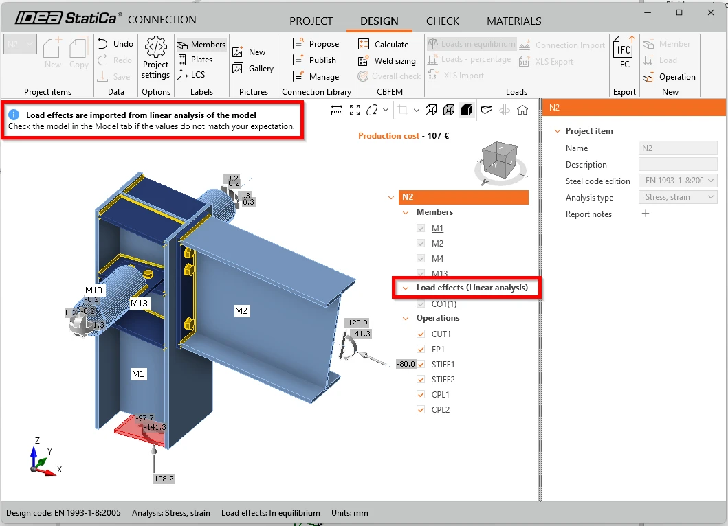
The connection check uses the ULS load effects calculated by the linear 1D analysis in Stability. There is no need for a transfer of forces between the structural model and the connection model.
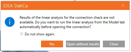
If the 1D analysis has not been performed yet, the user receives a notification about missing results.
For structures with repeated joints, an already designed connection can also be reused through Recent connections.
This closes an important gap between member stability and connection design. The analysis no longer needs to rely solely on an idealized joint assumption when the actual connection is designed elsewhere.
Instead, the connection that transfers the forces can be designed, checked, and subsequently represented by its actual stiffness in the stability analysis.
Verify the structure before looking for instability
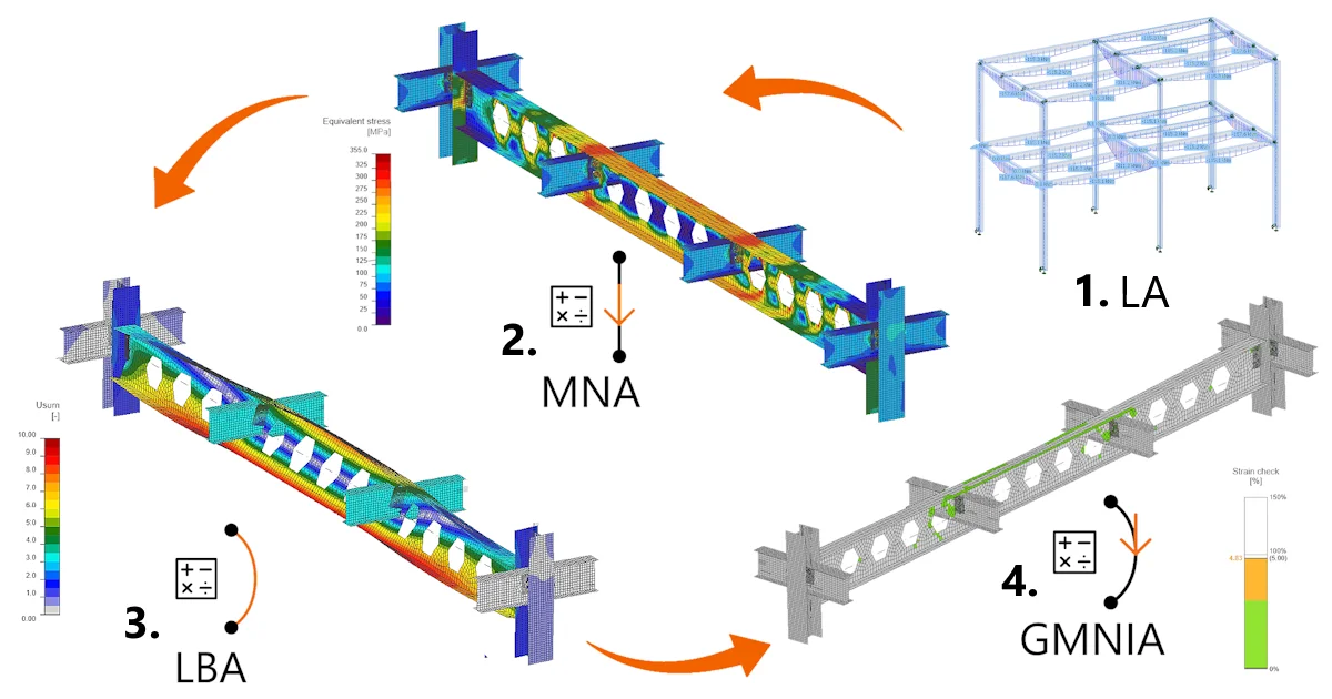
Before the stability analyses, a materially nonlinear analysis (MNA) is performed. The purpose is straightforward: verify that the structure, including the designed connections, can carry 100% of the applied load.
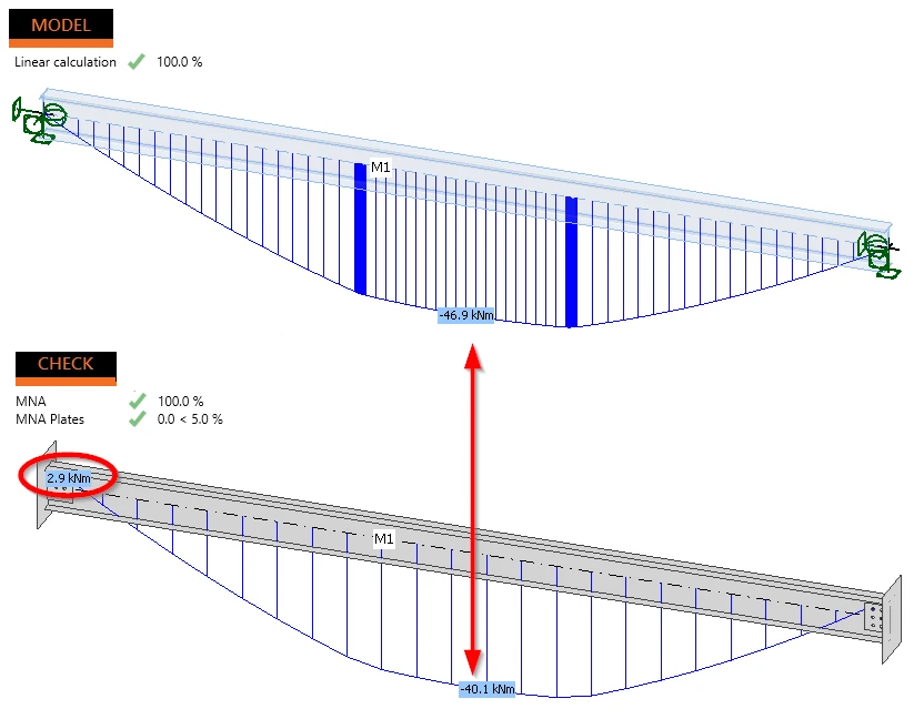
This creates a logical sequence of checks:
structural model → load transfer → connection design → MNA → stability analysis
The engineer, therefore, enters the stability assessment with a structural system whose geometry, loading, boundary conditions, and connections have already been verified.
Learn how to design connections in the Stability app in this article.
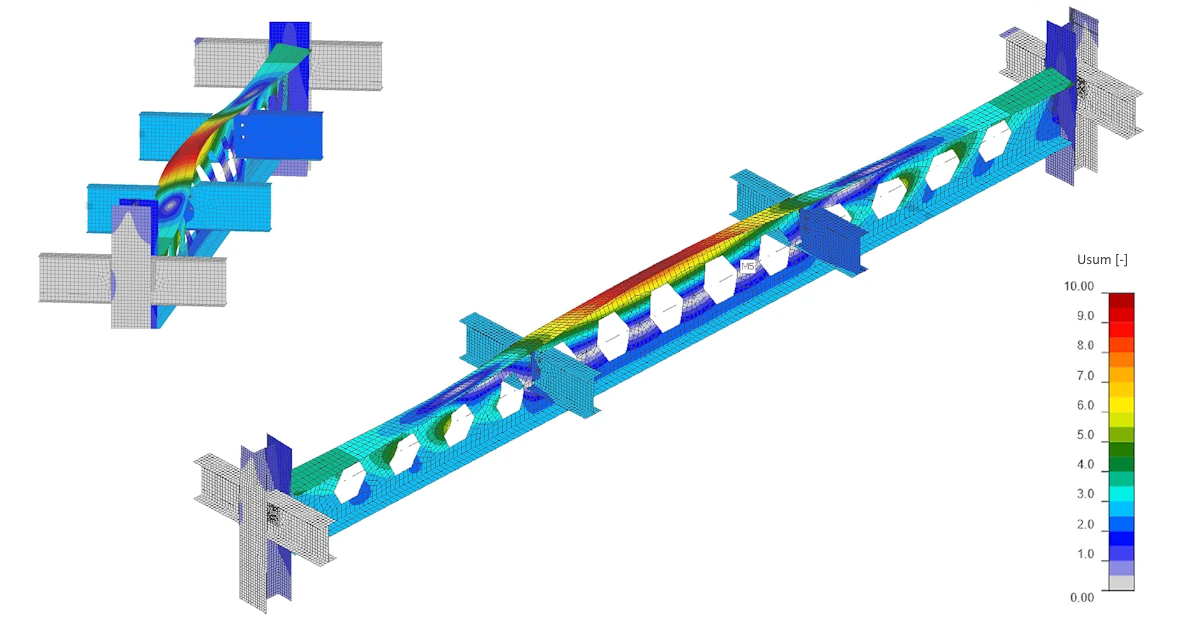
Buckling shapes - see how the structure buckles
The next step is a linear buckling analysis (LBA).
Instead of asking the engineer to anticipate a buckling mode or derive an effective buckling length beforehand, Stability calculates the buckling shapes of the modeled substructure.
Each shape is visualized directly on the structure together with its critical load factor αcr.

This provides both a numerical result and an engineering picture of the instability: the engineer can see whether the governing behavior is global, member-related, or local and how the surrounding structure participates in it.
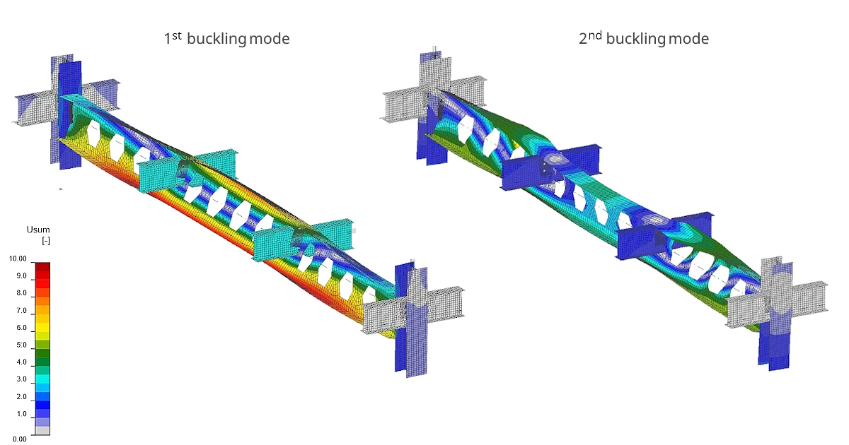
Because the analysis is performed on the modeled substructure, it takes into account its actual supports and the stiffness of the designed connections.
The critical load factor can consequently be used to obtain Ncr, Mcr, and the corresponding system length for use in a global structural model. It also helps determine whether second-order effects can be neglected in the global analysis.
If the critical load factor drops below 1.0, the applied load already exceeds the elastic critical load of the analyzed system – a condition clearly indicated in the results.
From buckling shapes to imperfections
A perfect numerical model does not buckle like a real structure. Therefore, advanced stability analysis requires imperfections.
Stability makes their definition visible rather than leaving it as an abstract numerical input.
Global imperfections can be introduced as an inclination or derived from the buckling shapes calculated by LBA. The available shapes are accompanied by their critical factors and indicators helping the engineer evaluate their relevance.
Selected buckling shapes can be combined with user-defined weights and amplitudes.
Most importantly, the resulting imperfect geometry is displayed directly in the 3D scene in millimeters before GMNIA is started.
The engineer can therefore inspect not only the magnitude of the imperfection but also its direction and combined shape.
This is particularly important when several imperfections interact. A buckling shape itself has no positive or negative orientation, while the chosen direction can affect the final resistance. Seeing the resulting geometry before calculation makes this engineering decision explicit.
Read more about imperfections in the Stability app.
GMNIA without deriving buckling lengths
With the imperfections defined, Stability performs geometrically and materially nonlinear analysis with imperfections (GMNIA).
This is the advanced-method route to the stability assessment: instead of deriving buckling lengths and then applying a member stability formula, the nonlinear response of the imperfect structure is calculated directly.
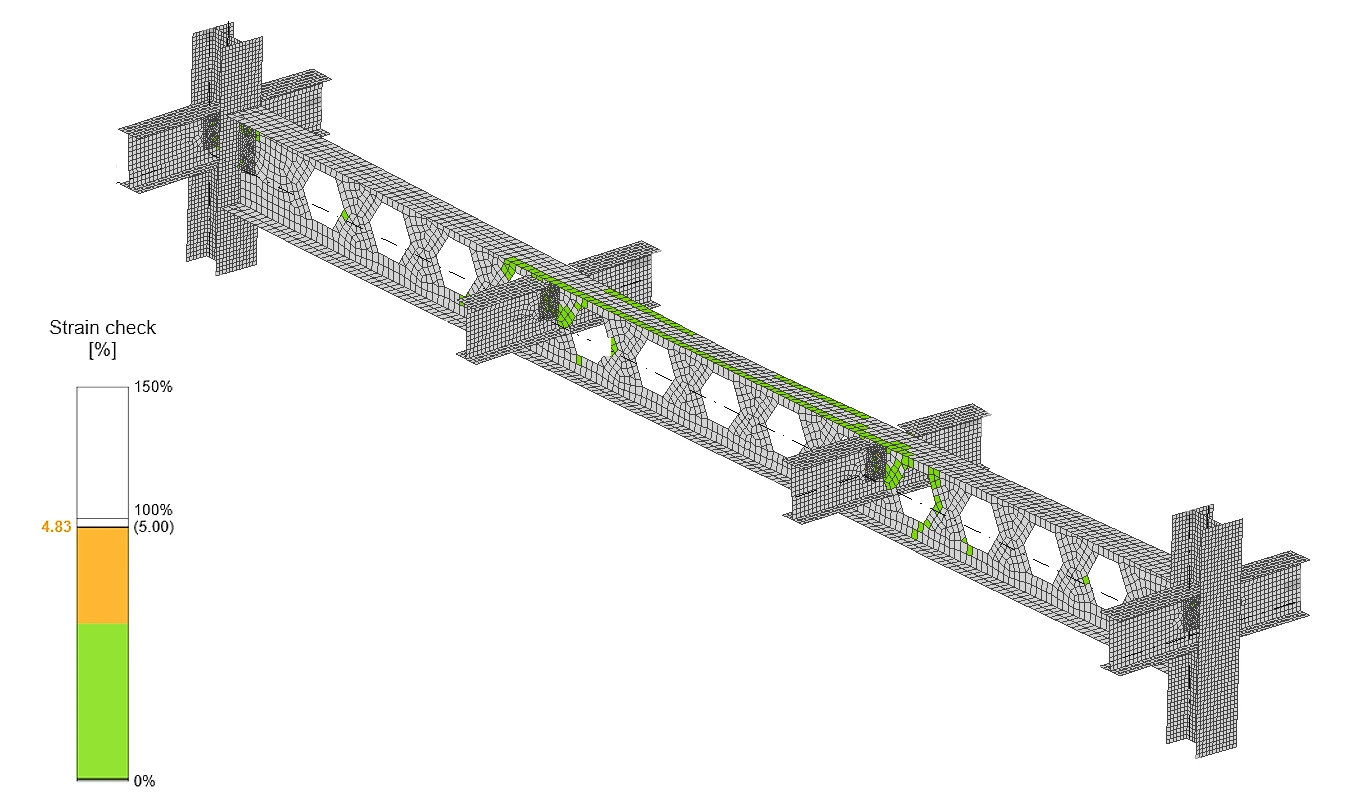
Results include strain check, stress, strain, and deformation components.
The analysis also provides settings for stiffness reduction according to the selected design code and a rotation limit for lateral-torsional buckling. The stiffness reduction affects GMNIA only; MNA and LBA remain unaffected.
The workflow therefore separates three distinct engineering questions:
MNA: Can the detailed structure and its connections carry the applied load?
LBA: How does the structure tend to buckle, and at what critical load factor?
GMNIA: Does the imperfect structure satisfy the stability assessment using the advanced analysis method?
Each analysis has its own results and an explicit OK / NOT OK status, so the conclusion does not have to be inferred from a collection of result tables.
The final report can cover the structural analysis and, when required, include the connection checks in the same document.
Find out more about all analysis types in Stability in this article.
Go directly from your global FEA model through Checkbot
In many projects, the member that requires a stability check already exists in a global FEA model.
There is no reason to build it again.
Stability is therefore integrated with IDEA StatiCa Checkbot. A relevant substructure can be taken from the imported global model and opened directly in Stability with its geometry, cross-section alignment, member eccentricities, load cases, combinations, and connections.
The modeling step is skipped and the Stability project opens directly in the Design stage (no Modeling of the 1D structure is needed; therefore, the Model tab is not visible)
This reduces manual transcription between the global analysis and the detailed stability assessment – and with it the risk that the model being checked differs from the model that generated the forces.
There is one important engineering input that remains with the user: the supports at the boundary of the extracted substructure. These boundary conditions represent the restraint provided by the surrounding structure and can significantly influence the stability result. They therefore need to be defined and verified by the engineer.
Connections first, stability second
When Stability is launched from Checkbot, the connection design remains managed by Checkbot.
Connections are designed there first, preserving connection groups and the relationship with the imported structural model. Stability then reads these designs and uses their stiffness in the stability assessment rather than modifying them.
The workflow is therefore intentionally simple:
Import global FEA model → design connections in Checkbot → select the substructure → open Stability → define boundary supports → run the stability check.
Checkbot keeps the status of the analyses, including MNA, the LBA critical factor, GMNIA, and plate checks, giving the engineer an overview of which stability projects have already been verified.
And when the imported substructure is not sufficient for the task, the project can be exported to a standalone Stability. There, the full Model tab becomes available again, allowing the engineer to extend or modify the structure and continue the analysis independently.
From an isolated member to the real structural system
Stability changes the question behind a member stability check - instead of asking:
“What buckling length should I assume for this member?”
...the engineer can investigate:
“How does this member buckle as part of the structure that actually restrains it?”
Editable substructure modeling, CBFEM members, code-checked connections, real connection stiffness, LBA buckling shapes, visible imperfections, and GMNIA are brought into one workflow – from the structural model to the final report.
That is the purpose of the new Stability application in IDEA StatiCa 26.1: to analyze buckling-prone members as part of the structure to which they actually belong.
Stability in your license
Stability is a part of the Complete product package. To welcome a new application, we offer it to Steel package users free of charge for a limited time period.
- Complete and Enterprise packages: Stability is included.
- Steel package: Stability is free until April 2027. From April 2027 (version 27.0), the full version of Stability is part of the Complete and Enterprise.
- Concrete and Detail package: Stability is not included.
Explore IDEA StatiCa Stability
Download the latest version to experience the Stability app on your own.
Download the latest version