
1 Starting a new project
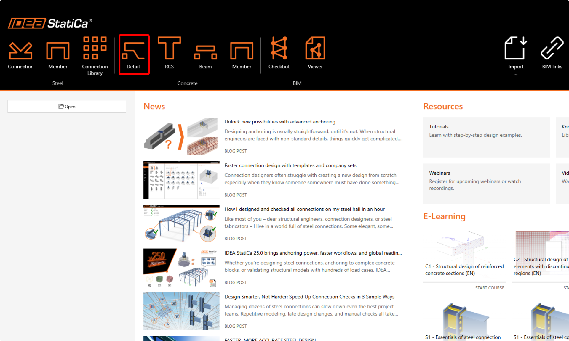
Let’s launch the IDEA StatiCa Detail application (download the newest version). In the main window of IDEA StatiCa, open the Detail application to start a new project.
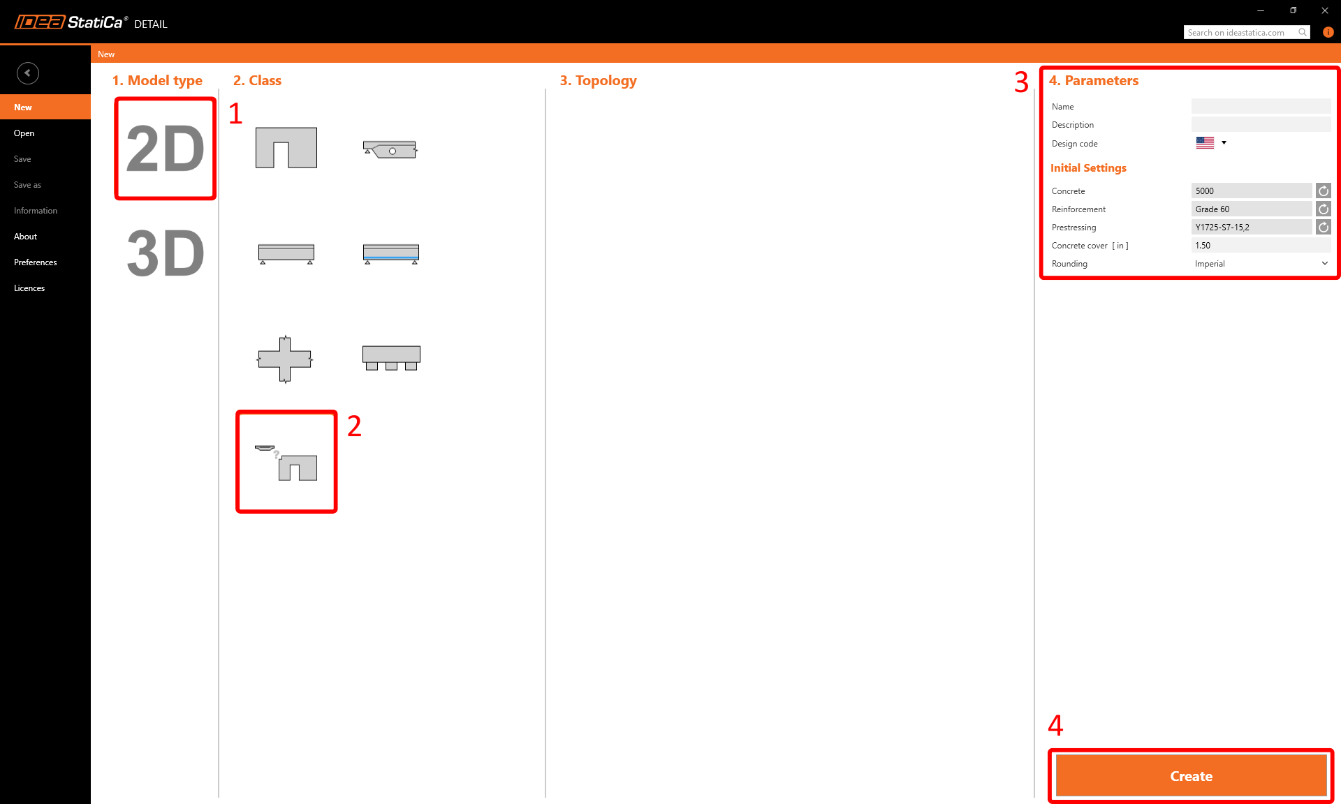
In this tutorial, we’ll create a walking column from scratch, so choose the option to start without using a template. However, templates can be very helpful for your future designs.
In this step, you also define the design code (choose ACI) as well as the concrete grade and cover (use concrete 5000 and cover 1.50 in). You can change your choice of material (or add another one) later. Nevertheless, the design code can be chosen only in this first step of the project.
2 Geometry
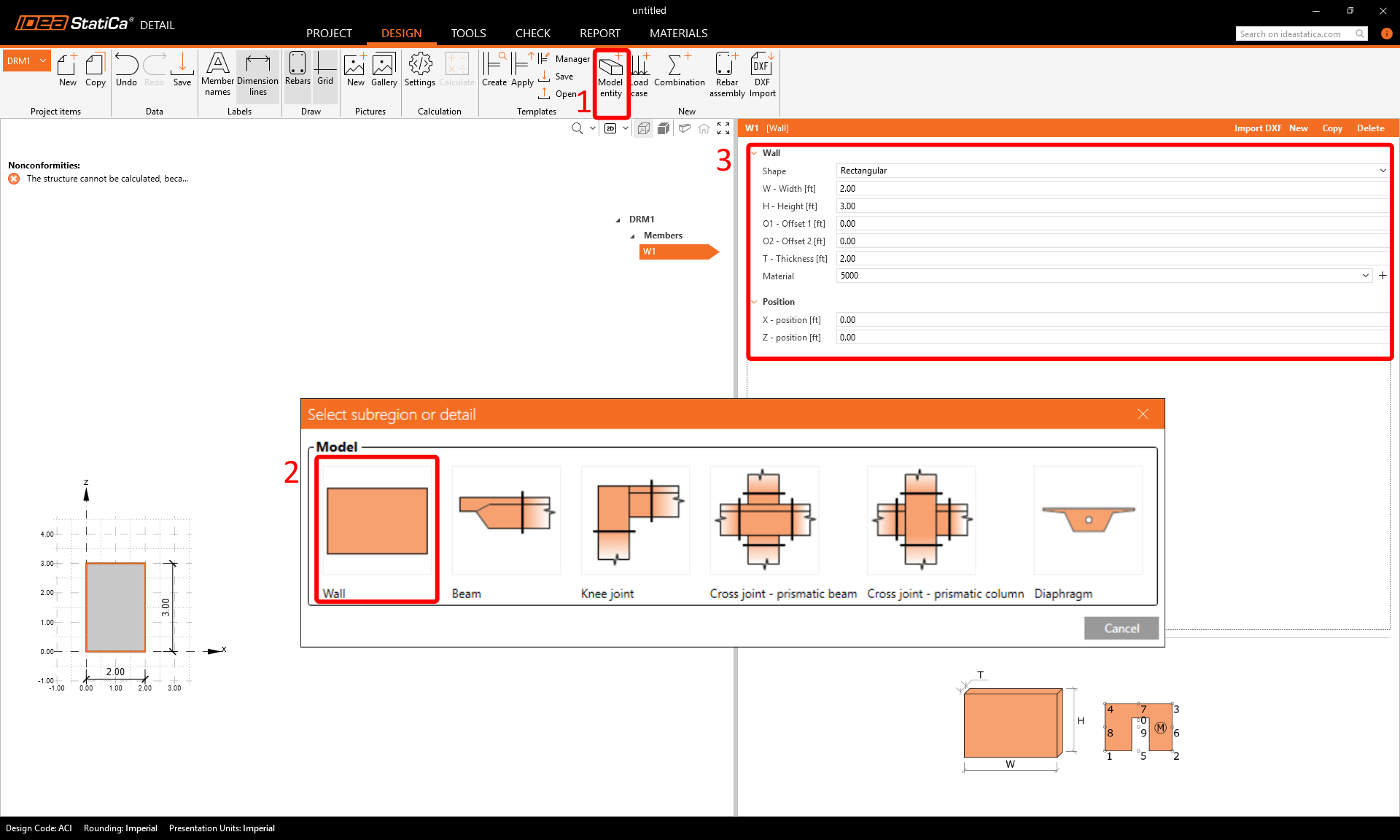
The Detail application will open with the Design tab automatically selected. You can define new items using commands in the top ribbon and then you can edit this items in the tree menu. If you want to get to know the application environment better, check out the following article - General interface in Detail application.
We will start with creating the Members. Use bottom in top ribbon to add a new model entity - Wall. Then, edit dimensions and position of the wall as shown in the image.
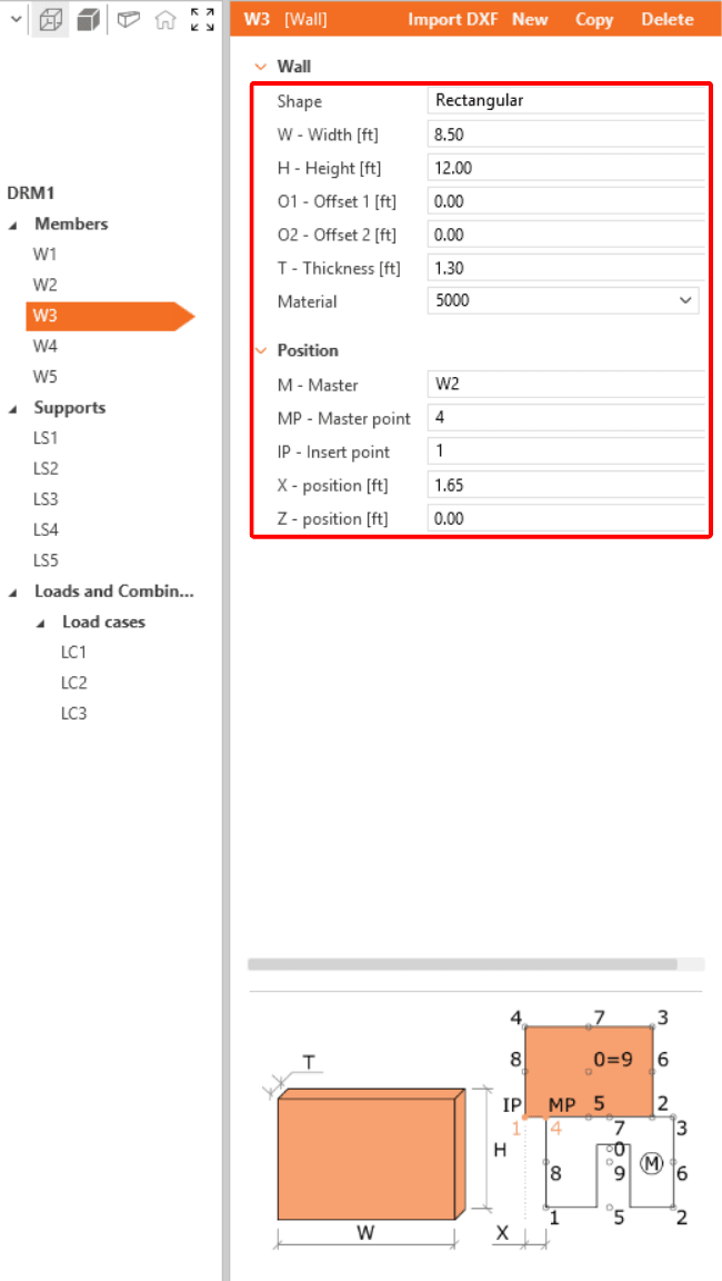
Repeat this process to create the additional wall entities W2-W5.


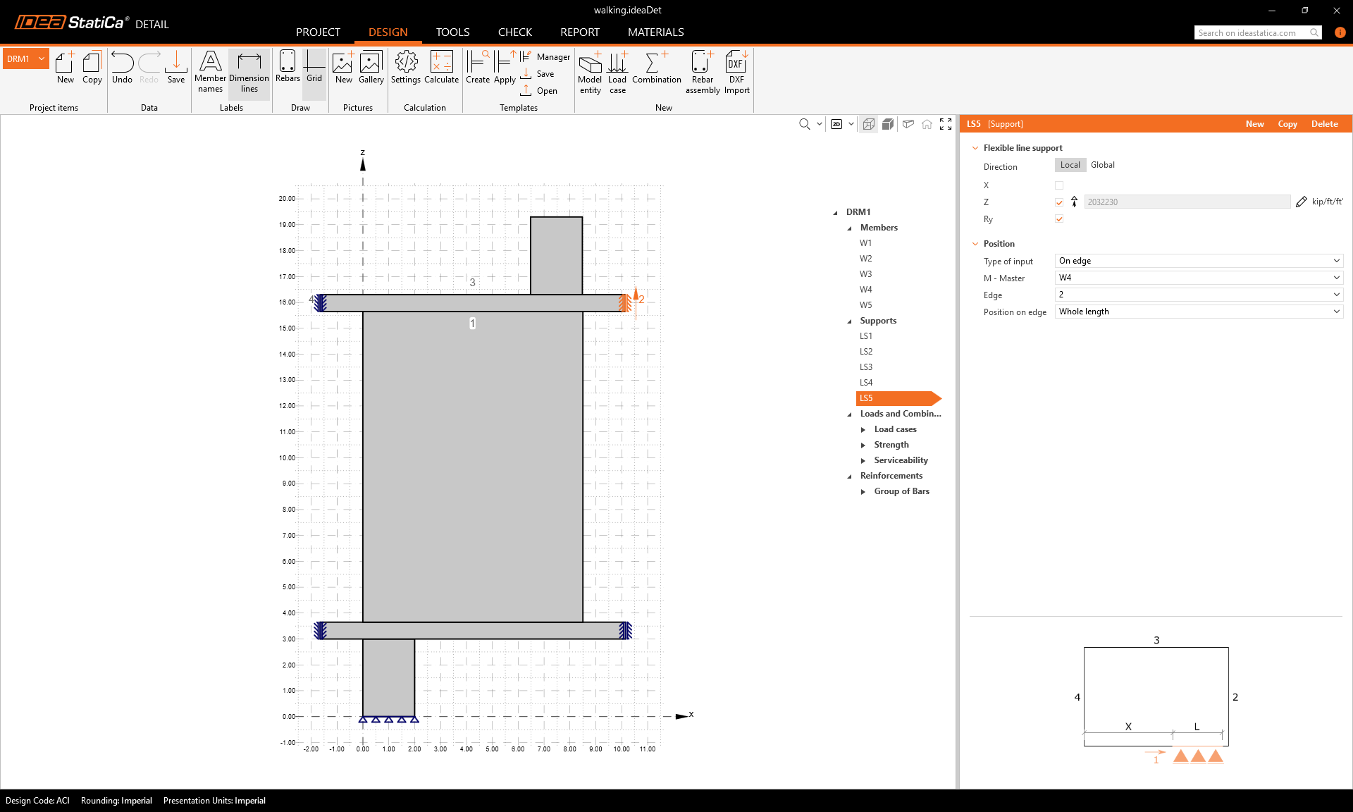
To finish the geometry, add supports. Again, insert a new model entity - this time choose Line support.
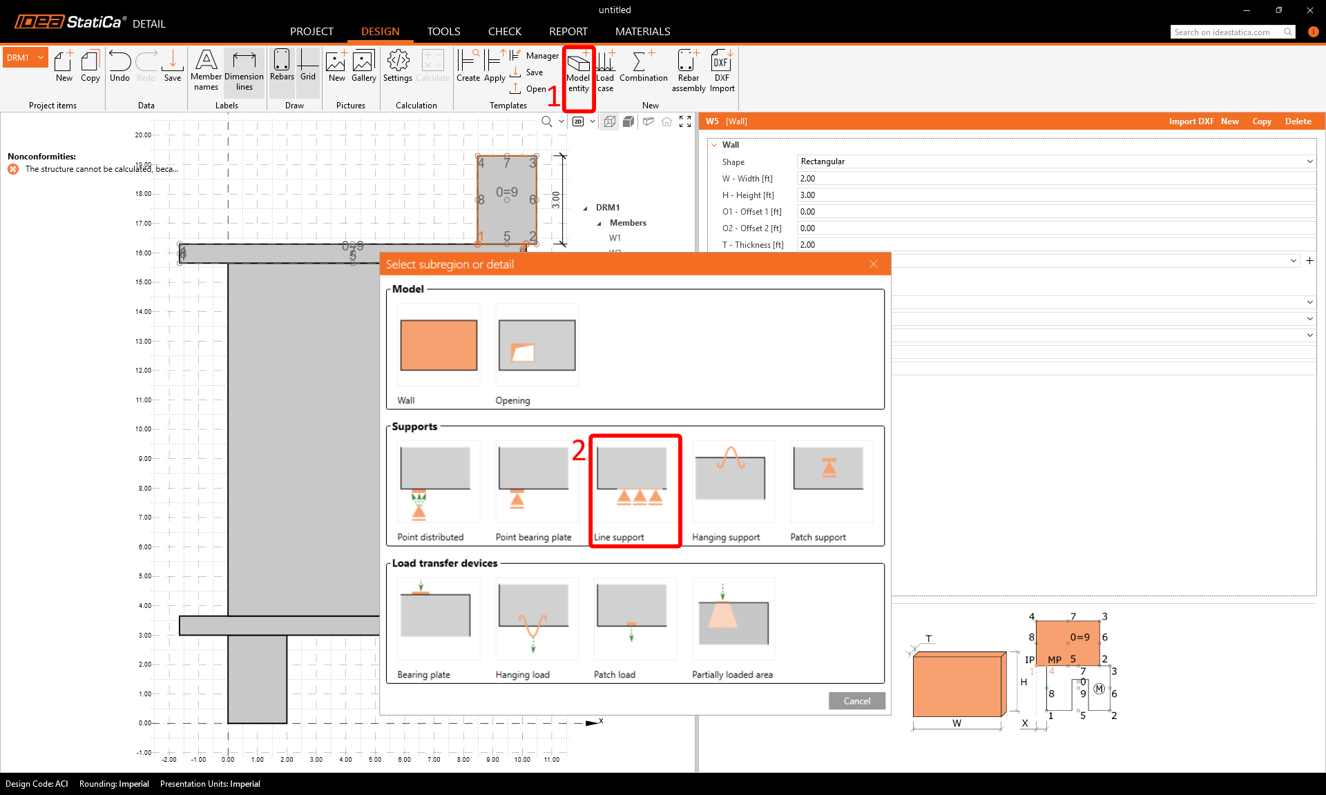
Just like when creating walls, set the parameters according to the image and repeat for LS2-LS5.


Your final geometry should now look like this:
3 Loads and Combinations
To add a load, click on Load case in the ribbon. A load case LC1 is created. Use the plus (+) button to insert a load impulse within this load case — choose Point Load and then repeat adding another load impulse with Self-Weight. Create two more load cases LC2 and LC3 with only Point load impulses.
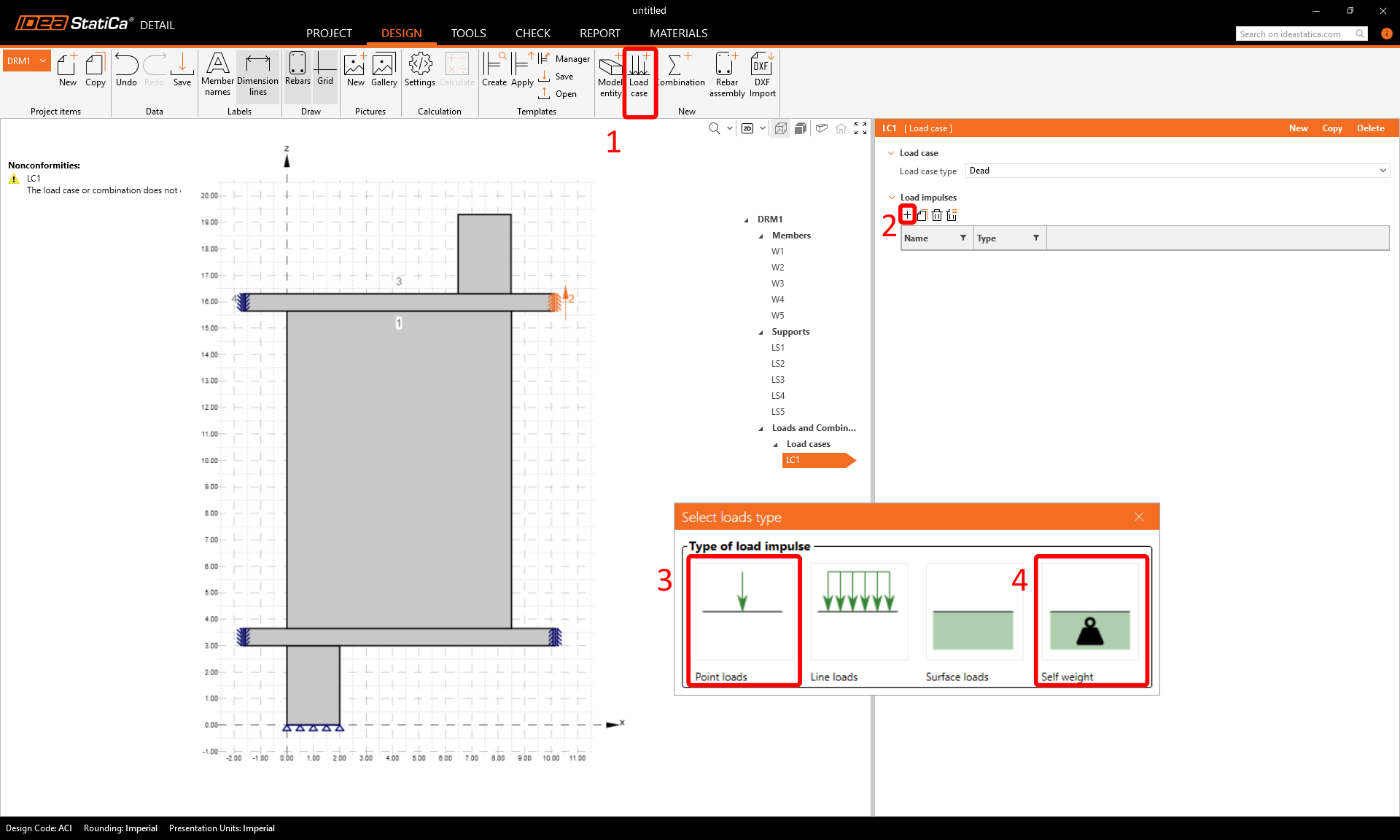
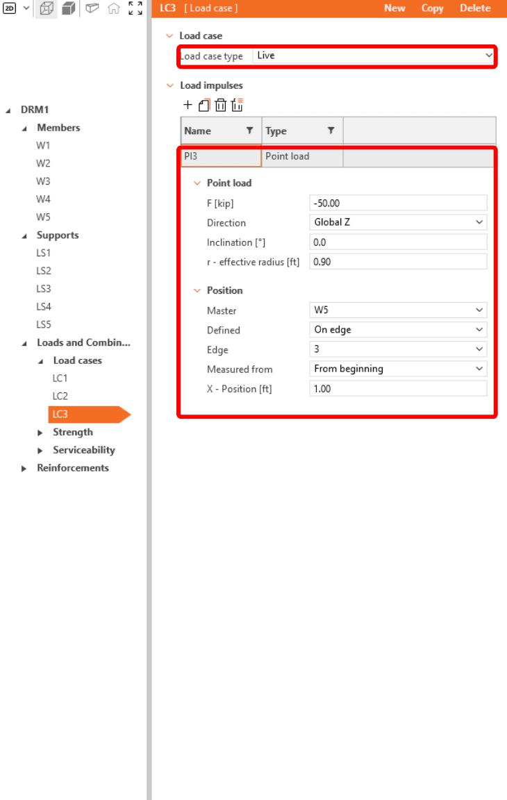
In order to be able to distinguish between short-term and long-term effects, make sure to correctly assign Dead and Live load case types and input the point load force values F and positions of the point forces according to the pictures.


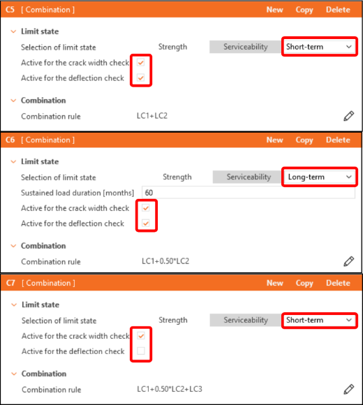
Load combinations can be created from the top ribbon command Combination. Add six combinations C1-C6, and then click on the pencil icon to edit the combination factors.

In the tree list, the combinations are divided into Strength (C1-C3) and Serviceability (C4-C6) groups. To activate crack width or deflection checks, tick the corresponding checkboxes in the property window under Serviceability combinations (C4-C6).
4 Reinforcement
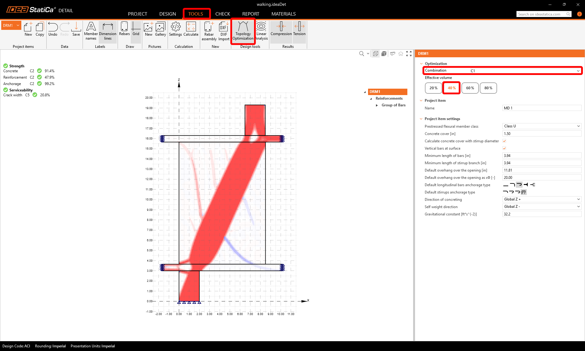
The next step is to reinforce the model. First, we can switch to the Tools tab and start the Topology Optimization in Design tools that help you to design the reinforcement (alternatively, you can use Linear Analysis).
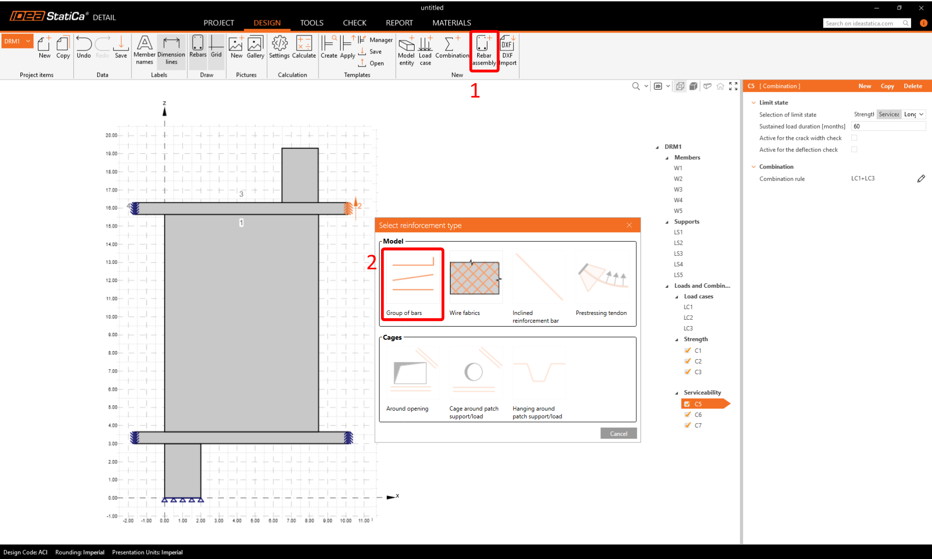
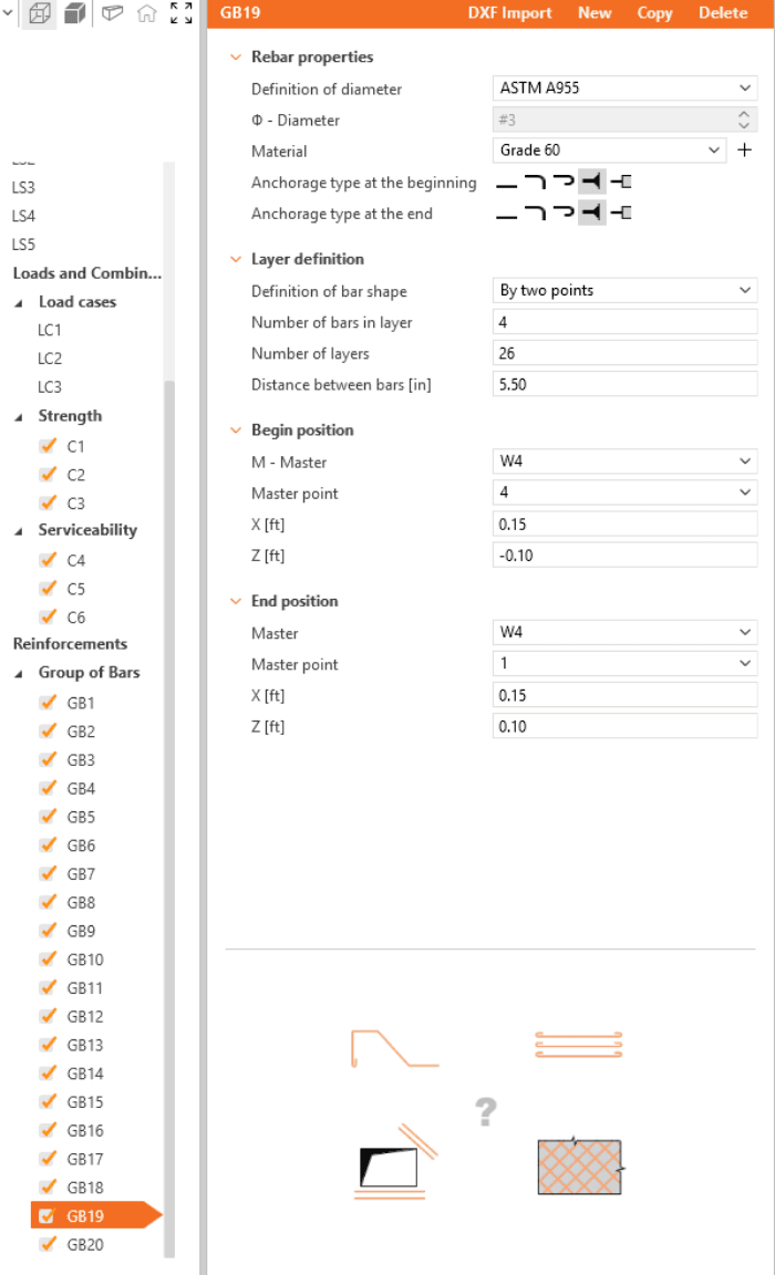
Now design the reinforcement. Click on the Rebar assembly in the section New. Select reinforcement type Group of bars.
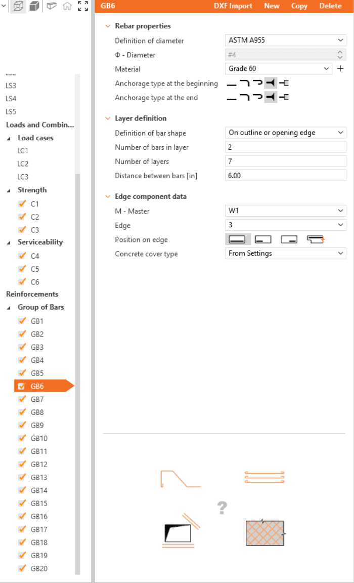
Define the properties of GB1, then repeat for GB2 to GB20. You can also use Copy to copy the current reinforcement.


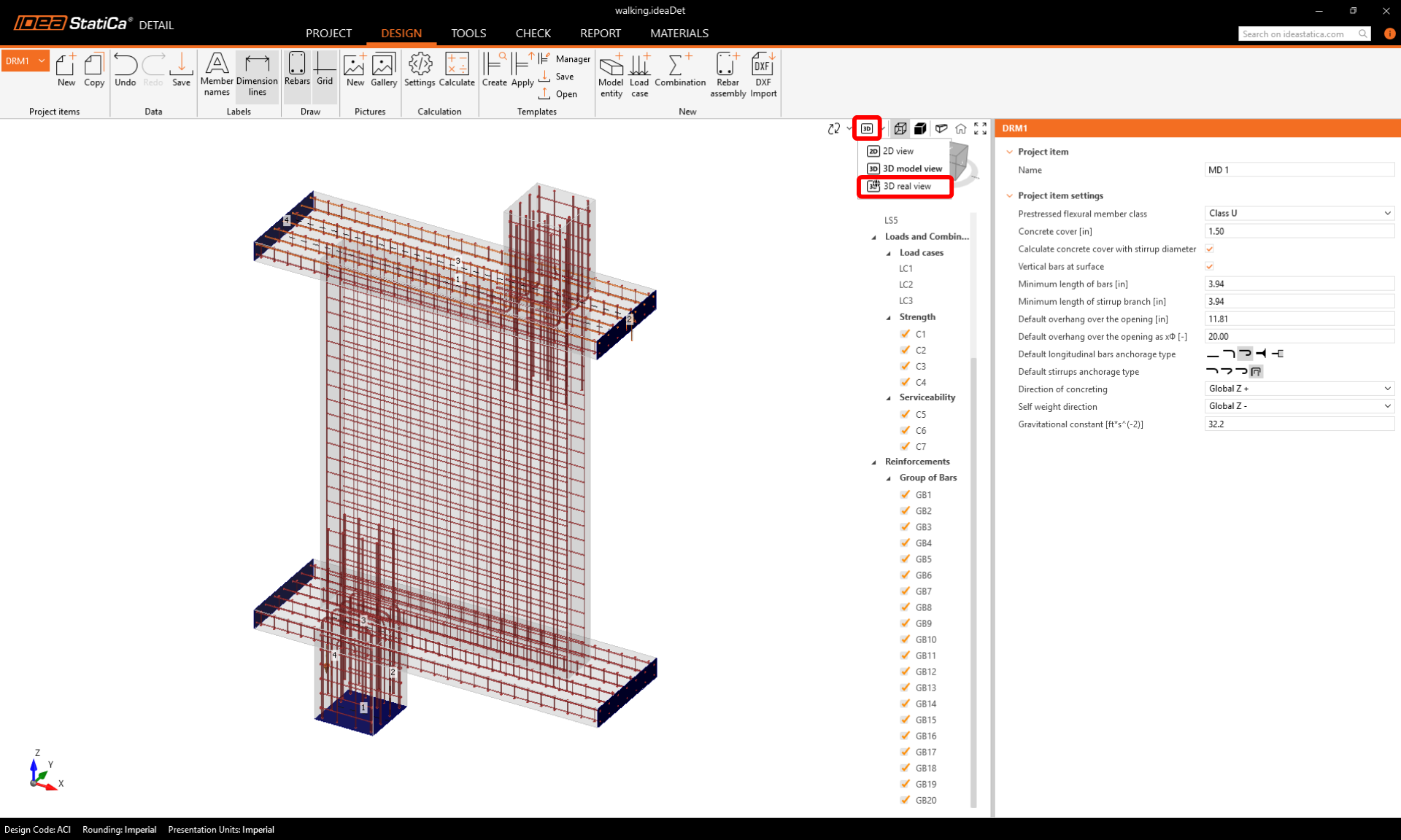
For a final check, switch back to the Design tab and choose the Real 3D View to inspect the rebar alignment visually.
5 Calculation and Check
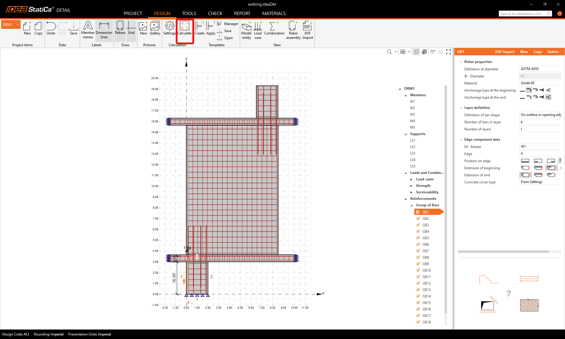
Start the analysis by clicking on the Calculate button in the ribbon.
The analysis model is automatically generated. Navigate to Check. On the left, you can see the overall results such as the material utilization.
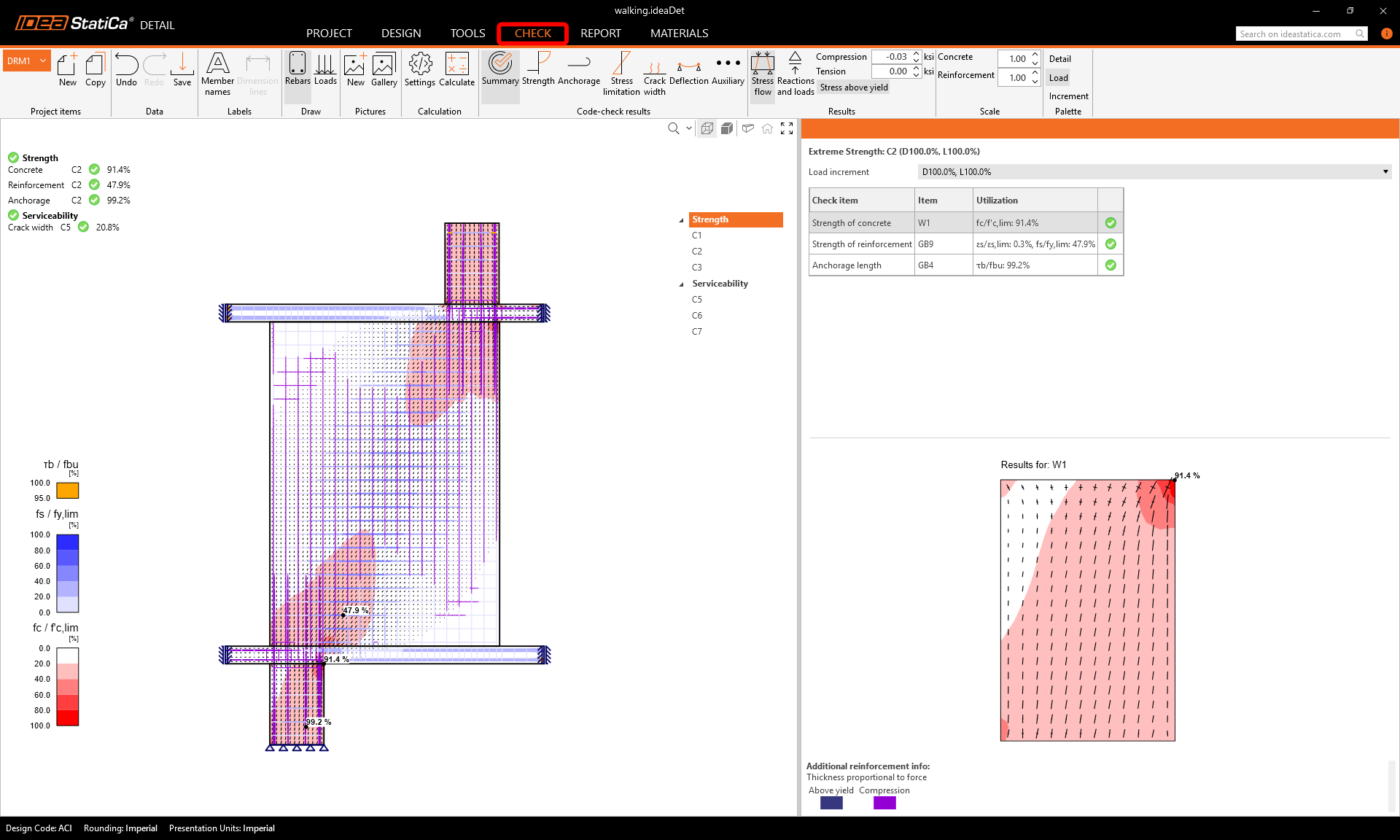
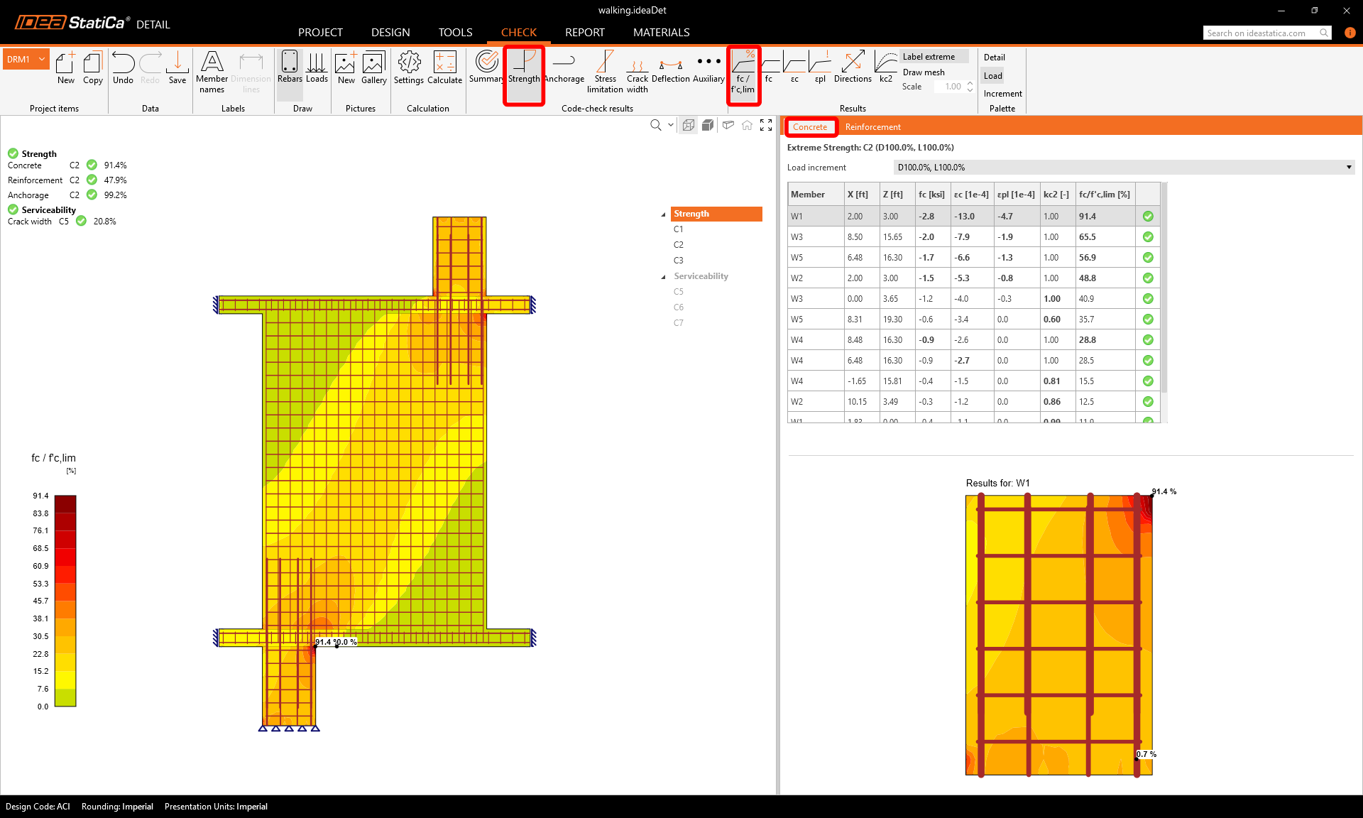
To go through the detailed checks of each component, start with Strength. This will show concrete checks such as utilization in stress, the direction of principal stresses and strains, which can be switched on in the ribbon. Also, you can change directions and scale of stress.
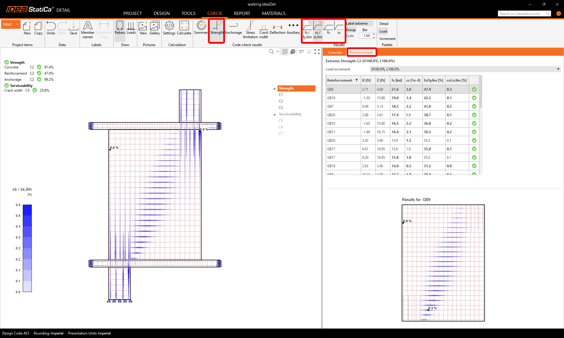
For detailed results of reinforcement, you need to switch to the Reinforcement tab. This will change the ribbon icons and also will unroll the table for results. You can display results for strains and stresses in each bar and their utilization.
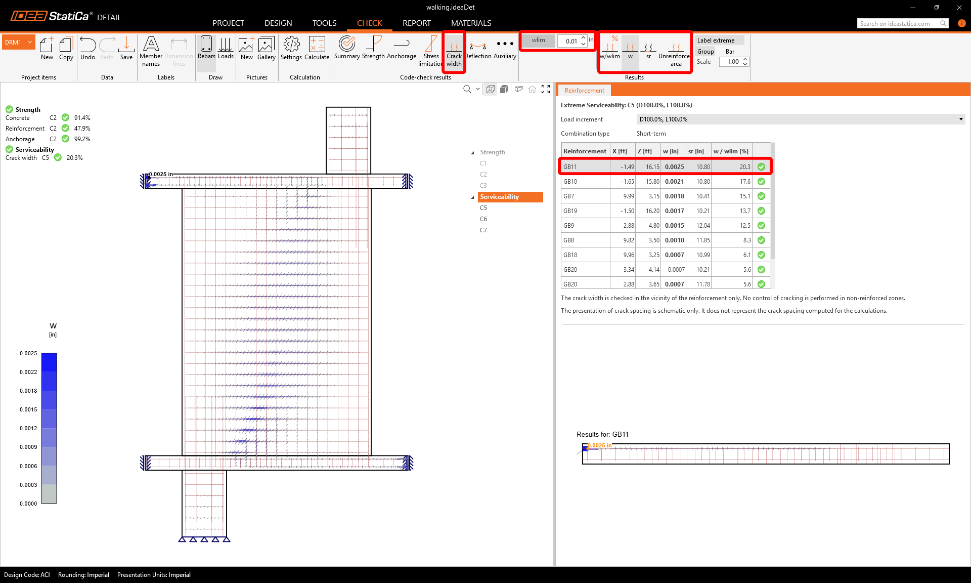
Let's go to the Crack limitation check. Besides the icons to switch between the results, there are settings in the ribbon to specify the limit value.
6 Printing report
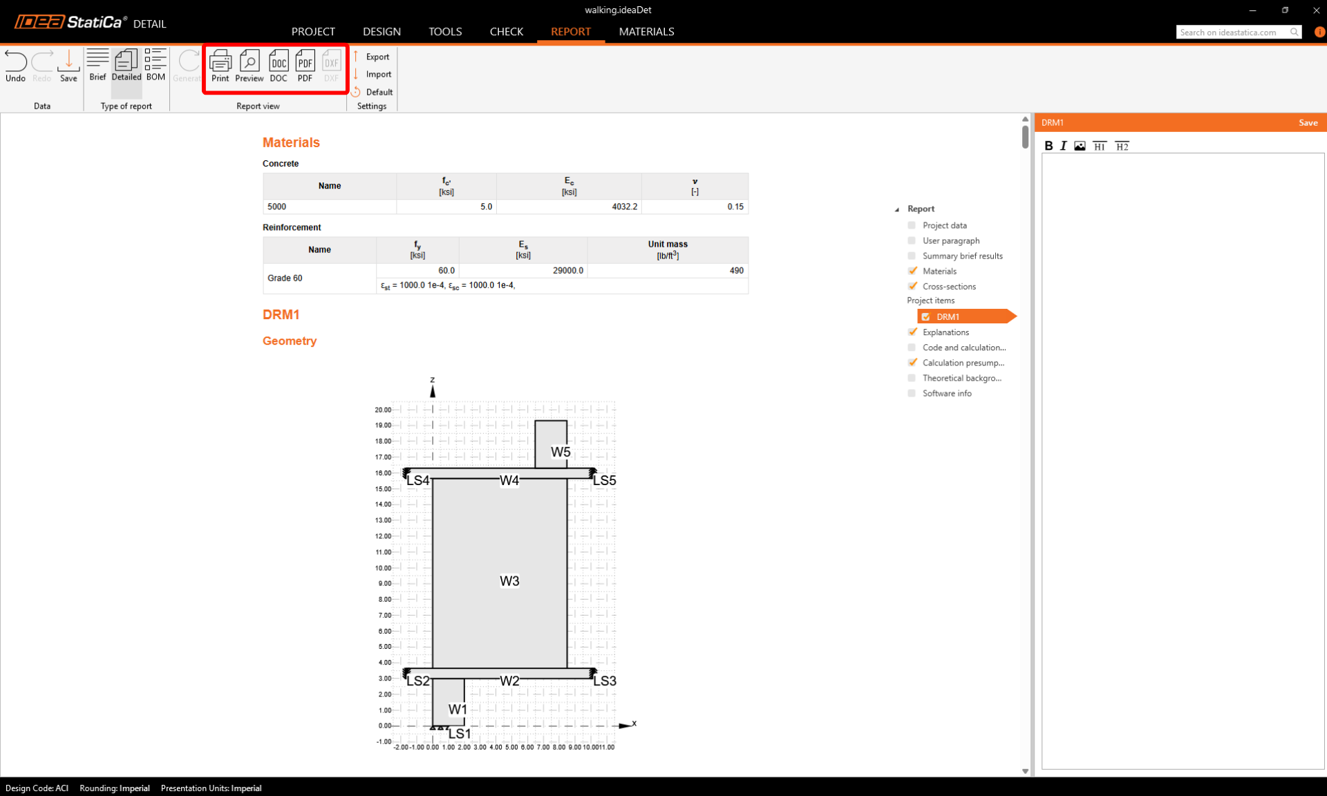
Now it is time to print a report of your calculations. Go to the Report tab. You can choose Brief or Detailed type of report and further adjust the report based on your needs in the tree menu. Select the preferred options and press Generate in the top ribbon.
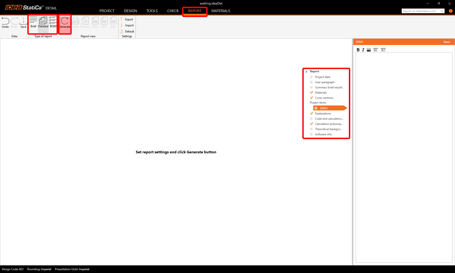
The report is generated, and we can save it as a PDF or export it to an open Microsoft Word file.
You have designed, optimized, and code-checked the reinforced walking column.
Learn how to use IDEA StatiCa effectively with our self-paced e-learning courses
Start learning