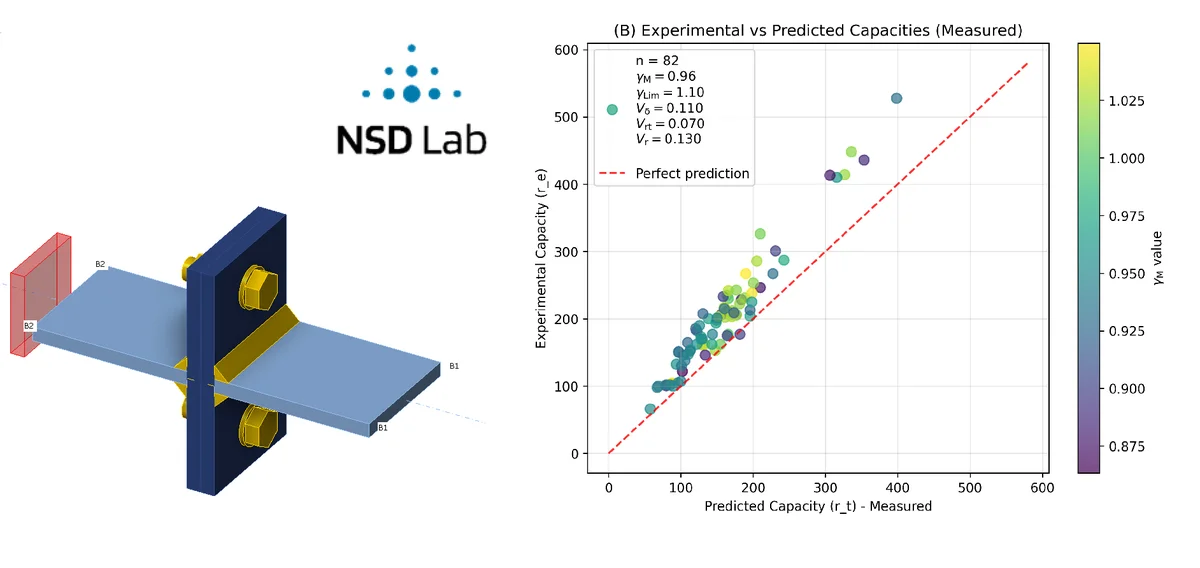
Summary of the experimental program
Steurer's ETH dissertation [1] addresses the rotation capacity of bolted end-plate connections, motivated by the lack of reliable models for deformation behavior needed to justify plastic redistribution in partial-strength connections. The dissertation discusses bolt types failing either by rupture or thread stripping. Most importantly, it contains three full-scale end-plate connection test series in Chapters 4 and 5 with detailed drawings, descriptions, and results in the Annex.
Varied parameters included connection type (flush/extended), end-plate thickness, bolt row number/arrangement, connected beam profile, and bolt preload level. Instrumentation captured moment–rotation curves, bolt row forces, and local end-plate deformation.
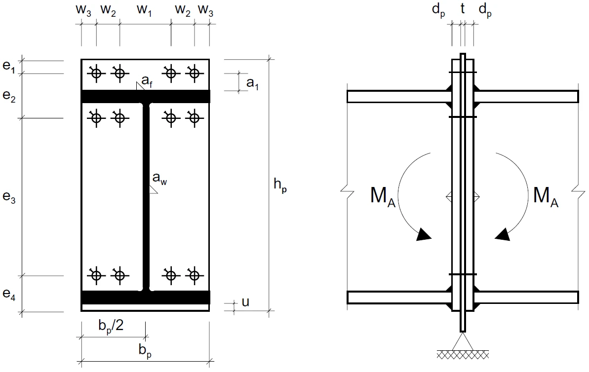
Typical end plate beam-to-beam connection from the test series [1]
Notably, HV bolts (EN 14399-4) were used. Such bolts are primarily meant for preloading, and due to their low nut thickness and manufacturing tolerances, they fail via thread stripping at smaller loads and elongations than standard high-strength bolts (EN ISO 4014 or EN ISO 4017) or HR bolts (EN 14399-3), as proven by D'Anielo et al. [2]. As such, they can be regarded as a worst-case scenario for end plate connections.
CBFEM models
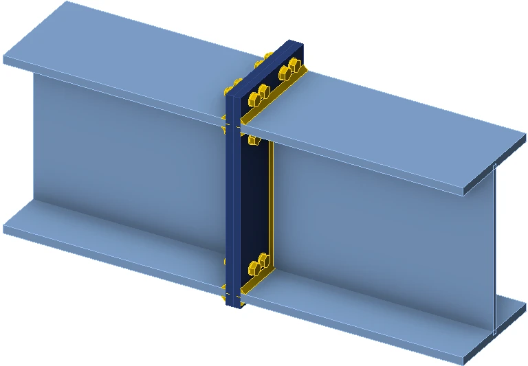
All the end-plate connections were modeled according to Steurer's dissertation using IDEA StatiCa Connection version 25.1.3. For experimental models, the plate material was converted to measured values, and the strengths used for bolts and welds were converted to mean values. All the safety factors were set to 1, increasing the plate and weld strengths compared to their standard design values.
Reliability assessment
The reliability assessment was performed according to EN 1990 and Safebrictile project [3]. This method requires three IDEA StatiCa models - with measured, nominal, and mean properties. To derive mean properties, Annex E of EN 1993-1-1:2024.
| fy multiplier | fu multiplier | |
| S235 | 1.25 | 1.2 |
| S355 | 1.2 | 1.15 |
| 8.8 | 1.1 | 1.1 |
| 10.9 | 1.1 | 1.1 |
Plate, weld, and bolt material properties were multiplied as shown in the table above to obtain mean models from nominal models. The partial safety factors are set to 1 with mean and experimental models but as default (e.g., ) for nominal models.
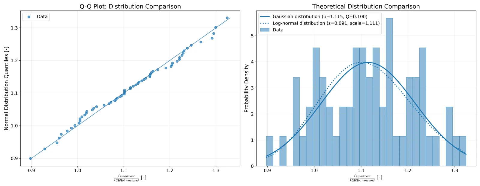
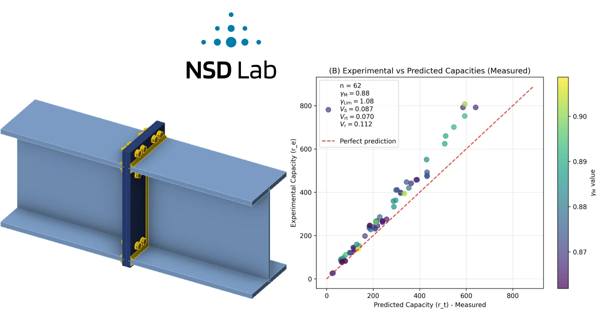
The experimental models show good alignment with the experimental results, and their ratios have a nearly normal distribution. The coefficient of variation, is added to the variation of the model due to basic variables, such as plate thickness or yield strength, , as used in standard Eurocode reliability assessments. was selected for 62 specimens. Some specimens were aggregated (similar experiments with nearly the same results) from the total of 111 experiments, so theoretically, even could be used.
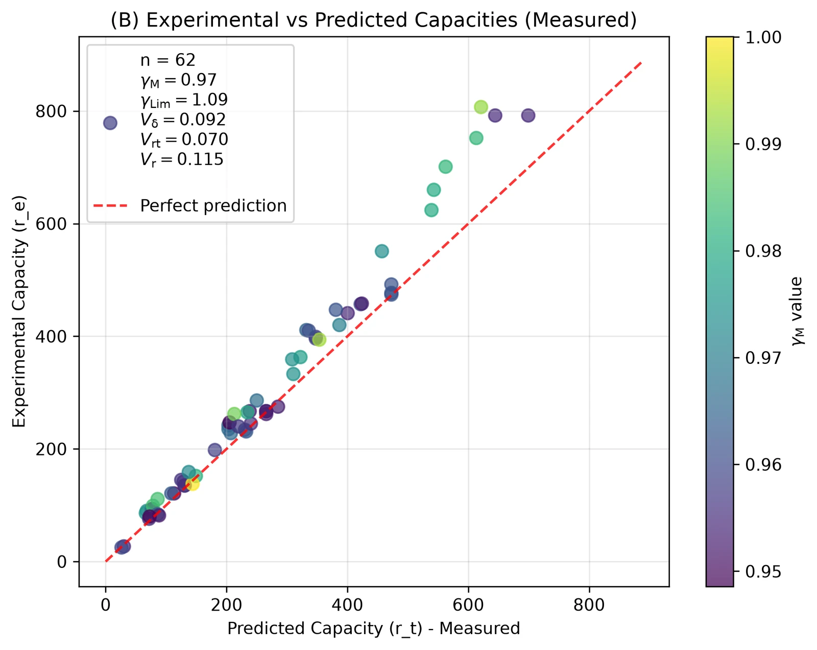
The design resistance obtained by the reliability assessment is calculated for each specimen, and the ratio of the resistance by the nominal model and reliable design resistance is the safety factor . The average of all specimens is accepted as the safety factor for the whole set.
The result is below the limit from Safebrictile [3] and also below 1. This means the nominal models from IDEA StatiCa provide reliable resistances closely aligned to the Eurocode reliability targets. The end-plate CBFEM numerical design calculations do not require any additional safety factor for numerical models.
Conclusion
In addition to extensive verifications, validation of end plate connections is presented based on an extensive testing campaign by A. Steurer at ETH Zürich. The experiments feature high-strength HV bolts that fail at lower tensile loads and at smaller deformations than standard ISO bolts. Nevertheless, the reliability assessment of IDEA StatiCa Connection models with nominal properties and default settings according to EN 1990 proves sufficient reliability .
References
[1] A. Steurer, Das Tragverhalten und Rotationsvermögen geschraubter Stirnplattenverbindungen, IBK Bericht Nr. 247. Basel, Switzerland: Birkhäuser, 1999. doi: 10.3929/ethz-a-003878456.
[2] M. D'Aniello, D. Cassiano, and R. Landolfo, "Monotonic and cyclic inelastic tensile response of European preloadable gr10.9 bolt assemblies," J. Constr. Steel Res., vol. 124, pp. 77–90, Sep. 2016, doi: 10.1016/j.jcsr.2016.05.017.
[3] European Commission: Directorate-General for Research and Innovation, Cajot, L.-G., Dehan, V., Dekker, R. W. A., Haremza, C. et al., Standardization of safety assessment procedures across brittle to ductile failure modes (SAFEBRICTILE) – Final report, Publications Office, 2017, https://data.europa.eu/doi/10.2777/76892