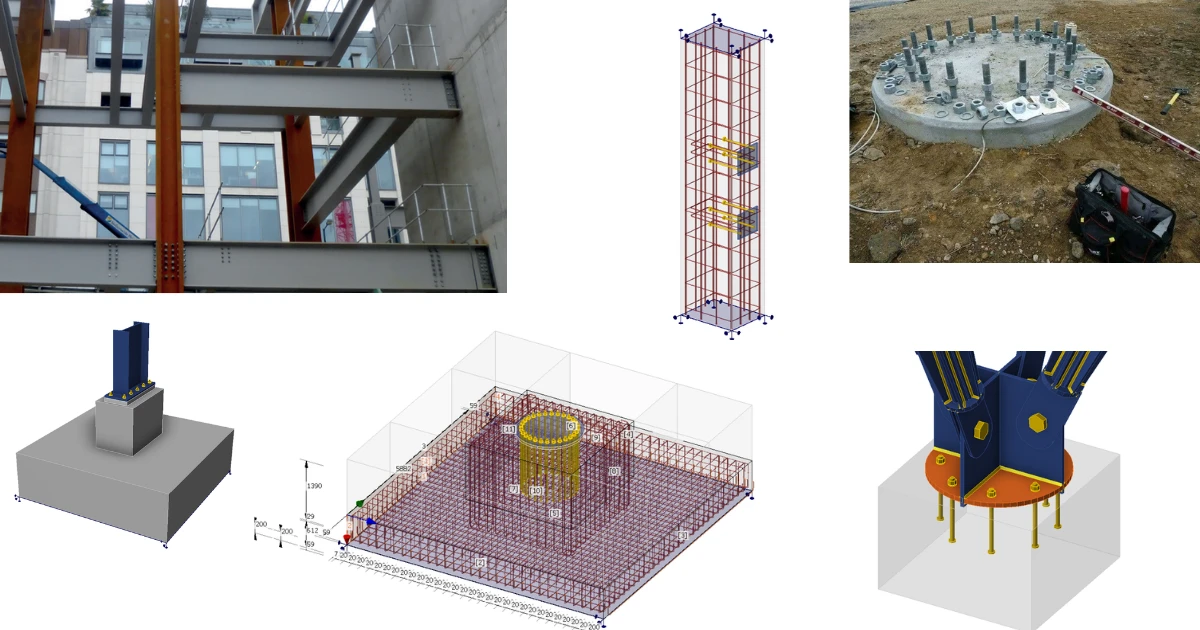


First, we will look at general anchor selection and standard applications, and then we will explore the challenging situations. Both can be solved using IDEA StatiCa for anchoring.
Best practices in anchorage design
There is no such thing as a universal "best" anchoring system. Proper structural design requires a much deeper understanding of the forces and conditions at play. Before selecting an anchoring system, here are the most critical factors you need to clarify:
- Load Type & Direction
- Load Distribution & Baseplate Behavior
- Installation Limitations & Construction Site Conditions
- Regional Standards & Code Requirements
Cast-in plates vs. Base Plate
When designing steel-to-concrete connections, we first need to distinguish between two fundamental structural interfaces: cast-in plates (embed plates) and traditional column base plates. Cast-in plates are embedded flush with the concrete surface during casting, allowing steel members to be welded laterally or beneath the concrete. In contrast, a classic base plate serves as the primary structural footprint attached to the bottom of a column, transmitting vertical loads, bending moments, and shear forces directly down into a concrete foundation.
Cast-in plates
Their biggest advantage is exceptional load capacity and immediate field-readiness—allowing structural steel members to be welded directly to the concrete framework without drilling post-installed anchors.
- The main drawback lies in their zero-tolerance nature. Embed plates require meticulous pre-planning and placement precision in the formwork, as fixing a misaligned plate after the concrete has cured is exceptionally difficult and expensive. Improper concrete compaction around the anchor studs can also leave hidden voids that compromise structural integrity.
Despite these installation challenges, cast-in plates remain the go-to solution for joining steel beams to concrete cores, securing curtain wall facades on high-rises, and mounting heavy equipment or pipe racks in industrial facilities where flush, high-capacity welding points are essential.
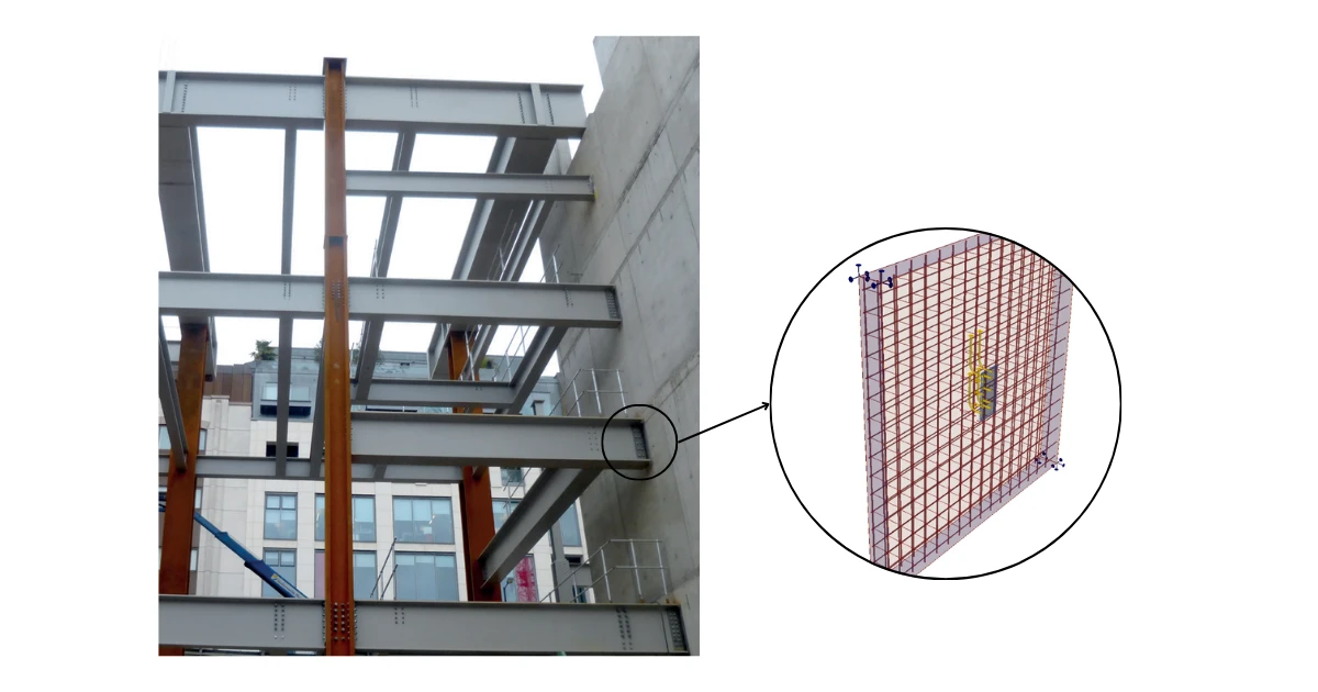
When designing cast-in plates (embed plates) in IDEA StatiCa, selecting the right anchoring elements depends entirely on the primary direction of the applied forces. The software allows you to configure hooked anchors to effectively resist tensile pull-out forces deep within the concrete reinforcement, while headed studs or shear lugs are utilized to transfer high shear loads through direct bearing action. For complex multiaxial loading involving simultaneous tension, bending, and shear, IDEA StatiCa enables a combined configuration of these components to deliver an optimized and fully verified structural connection.
Base plates
A base plate is the primary interface connecting a structural steel column to a concrete foundation. Since steel profiles are thin and carry heavy axial forces, bending moments, and shear, placing a raw column directly on concrete would cause local crushing. The base plate widens the contact area to distribute these stresses safely.
Cast-in-place anchors vs. Adhesive (Chemical) anchors
Cast-in-place anchors
When using cast-in-place anchors—installed in the formwork before pouring concrete—you choose between three main types depending on the load path:
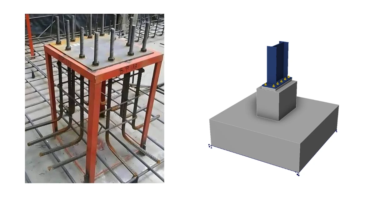
- Washer plates – The standard detail for steel column bases, where the base plate sits on grout over anchor rods cast into the foundation. Thick steel plate at the bottom of a threaded rod engages a massive concrete breakout cone, making them ideal for heavy industrial frames with high uplift forces. The holes in the base plate are oversized to accommodate misplaced rods. The main benefit is erection tolerance, plus proper load spreading when the rods carry tension from moment or uplift. The drawback is that the oversized holes leave slip under shear.
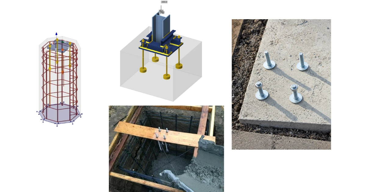
- Headed studs – Studs are welded to a plate. Steel parts are welded onto it, for example beams framing into concrete walls or cores, façade brackets, or precast connections. The benefits are a clean, flush detail with no grout or nuts and good shear transfer. The drawbacks are zero erection tolerance, because the position is fixed at casting, and clashes with reinforcing bars, especially for the first row of studs near the edge of a plate. Short embedment means concrete breakout often governs.
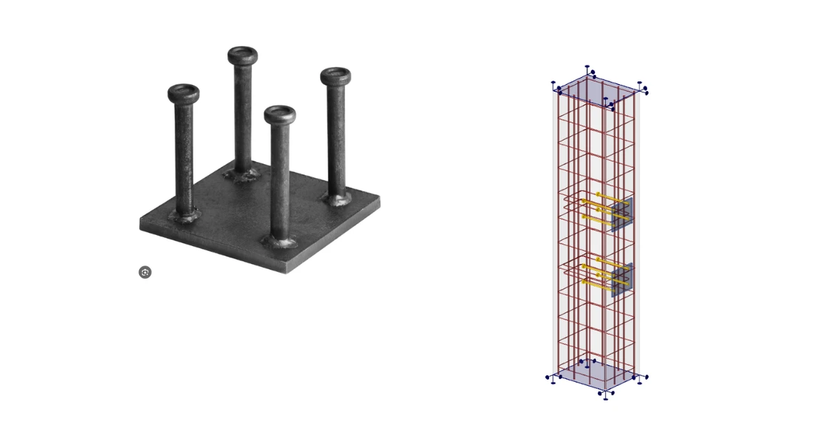
- Embedded reinforcement – These work like stud embeds, but with rebars welded to the plate that anchor by bond over a longer length. They are used for high tension loads, thin members, or edges where a stud’s breakout cone is too small, and where the force should lap into the member’s main reinforcement. The benefits are higher capacity and a direct load path into the reinforcement, with no reliance on the concrete’s tensile strength. The drawbacks are long bars that are hard to coordinate with existing reinforcement, the need to confirm the rebar is weldable, and the same lack of tolerance.
Adhesive anchors
Conversely, post-installed adhesive (chemical) anchors use a threaded rod set in two-component resin after the concrete has cured. They are the go-to choice for retrofits, building expansions, or correcting misplaced bolts because they can be drilled wherever needed. Since chemical anchors transfer load via continuous bonding without creating expansion pressure, they excel near concrete edges and in tight anchor groupings. However, they require meticulous hole cleaning, are sensitive to high temperatures and fire, and need curing time before loading.
We have covered the basic anchoring options, and all of them can be designed directly in IDEA StatiCa Connection. Standard, day-to-day cases like these are straightforward to handle, but real projects are rarely that simple.
Tricky anchorage details
Beyond best practices, edge cases and tricky scenarios inevitably come up in real-world design. Fortunately, with the right tools, most of them can be solved reliably. Let’s look at some of the most common ones.
Reinforced concrete and complex geometries
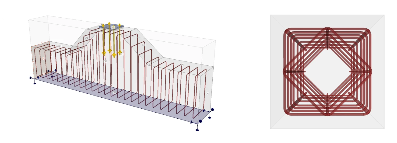
Whether anchoring into existing structures or dealing with cases where concrete is susceptible to failure—and due to tight or confined space conditions, standard concrete checks would fail on concrete breakout (cone failure) or other modes—it is crucial to account for the effect of reinforcement. IDEA StatiCa Detail enables verification of these complex cases. In the latest version, the modeling capabilities have been refined so that any shape can be reinforced, utilizing reference planes for geometry alignment and other advanced tools.
Code and regional requirements
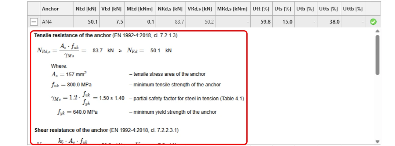
Navigating the differences between design codes and picking the right one can easily get overwhelming at times. When designing anchorages in IDEA StatiCa, you can easily select the governing design code to match your regional practice and the chosen anchor type—whether using EN 1993-1-8 for standard threaded bolts, EN 1992-4 for headed studs, or EN 1992-1-1 for reinforcement bars. The software ensures total engineering transparency by providing detailed check reports complete with every applied code formula, substituted value, and intermediate calculation step. With the release of version 26.1, transparency is further enhanced through comprehensive reporting.
Stand-off gaps
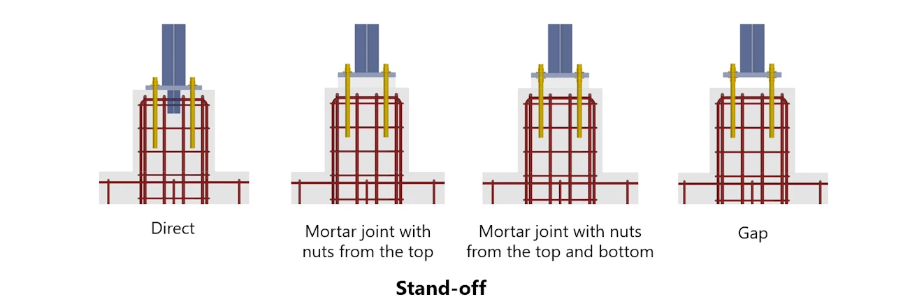
Both IDEA StatiCa applications–whether handling simple plain concrete checks in Connection or utilizing the full workflow with Detail via the 3D CSFM and comprehensive reinforcement design–reliably analyze complex cases like pedestals or stand-off installations with a gap. While a grouting gap significantly alters anchor bending moments and pressure distribution, combining both tools accurately captures prying effects in the fasteners and tracks how forces propagate into the underlying concrete block.
Multi-directional (Multi-plate) anchoring
When anchors and loads interact within a single concrete mass, analyzing each anchor group or connection separately can give unrealistic, often unconservative results. This applies not only to loads acting in multiple directions but also to several base plates or embed plates placed close to each other in the same concrete block. Their failure cones overlap, their stress fields interact, and the capacity of one plate is reduced by the presence of the others.
Superimposing independent calculations ignores these stress overlaps, the shared concrete volume, and the multidirectional shear/tension interactions.
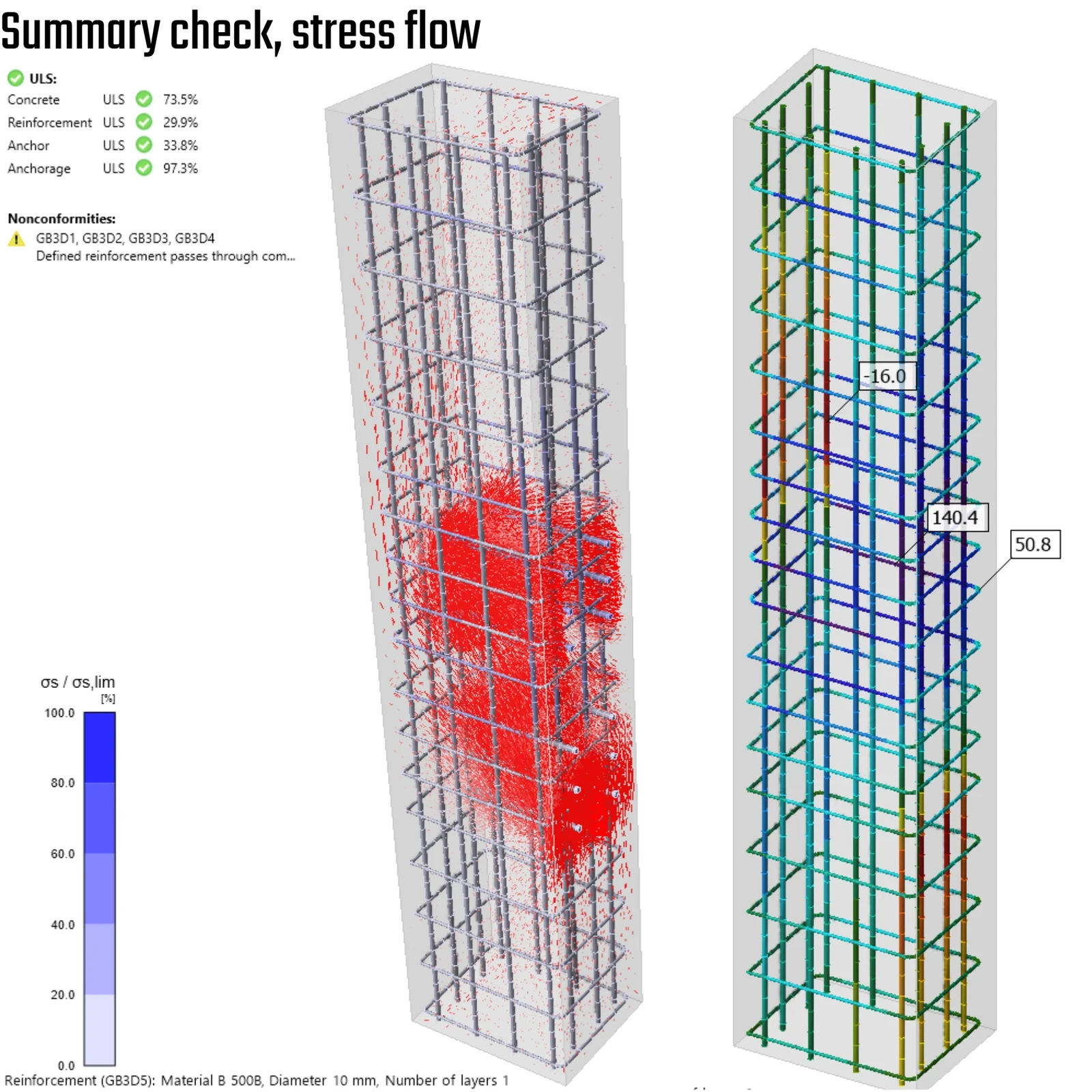
IDEA StatiCa addresses this with 3D CSFM in IDEA StatiCa Detail: instead of checking each base plate separately, all plates, anchors, and the reinforced concrete block are analyzed together as one model, so their interaction is captured directly. Specific tips and tricks for modeling these situations are covered in the following article.
Conclusion
Successful anchorage design starts long before software modeling—it begins with choosing the right anchoring strategy for the specific project requirements. Understanding the trade-offs among cast-in plates for flush welding, traditional base plates for column foundations, and cast-in-place vs. post-installed adhesive anchors sets the foundation for a safe and cost-effective structure.
While standard base plates and uniform anchor layouts can be designed effortlessly using standard code formulas and IDEA StatiCa Connection, real-world engineering routinely introduces complex edge cases. Whether dealing with stand-off gaps, multi-directional load interactions on a shared foundation block, or non-standard geometries requiring custom reinforcement, traditional empirical checks reach their limits. By leveraging the advanced CSFM capabilities of IDEA StatiCa Detail, engineers can confidently bridge the gap between standard best practices and complex, non-standard anchorage details—delivering fully verified, code-compliant, and transparent structural designs.
Design your next anchorage with confidence
Check base plates, cast-in plates, and adhesive anchors in Connection, then verify tricky details with reinforcement in the Detail app. Try it on your own project.