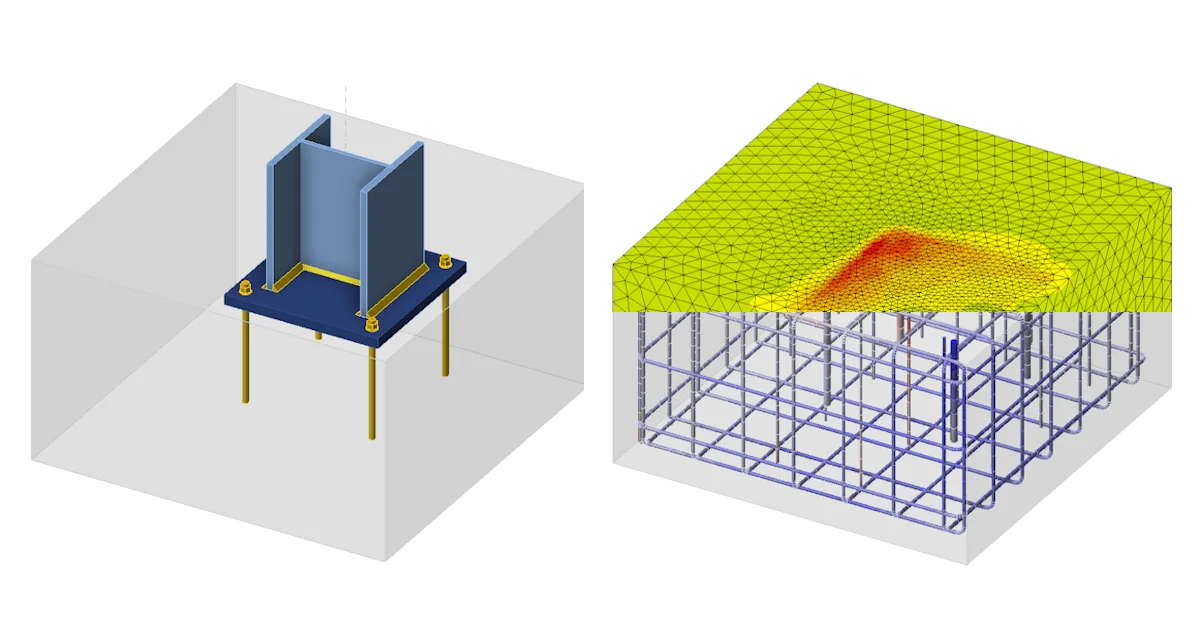
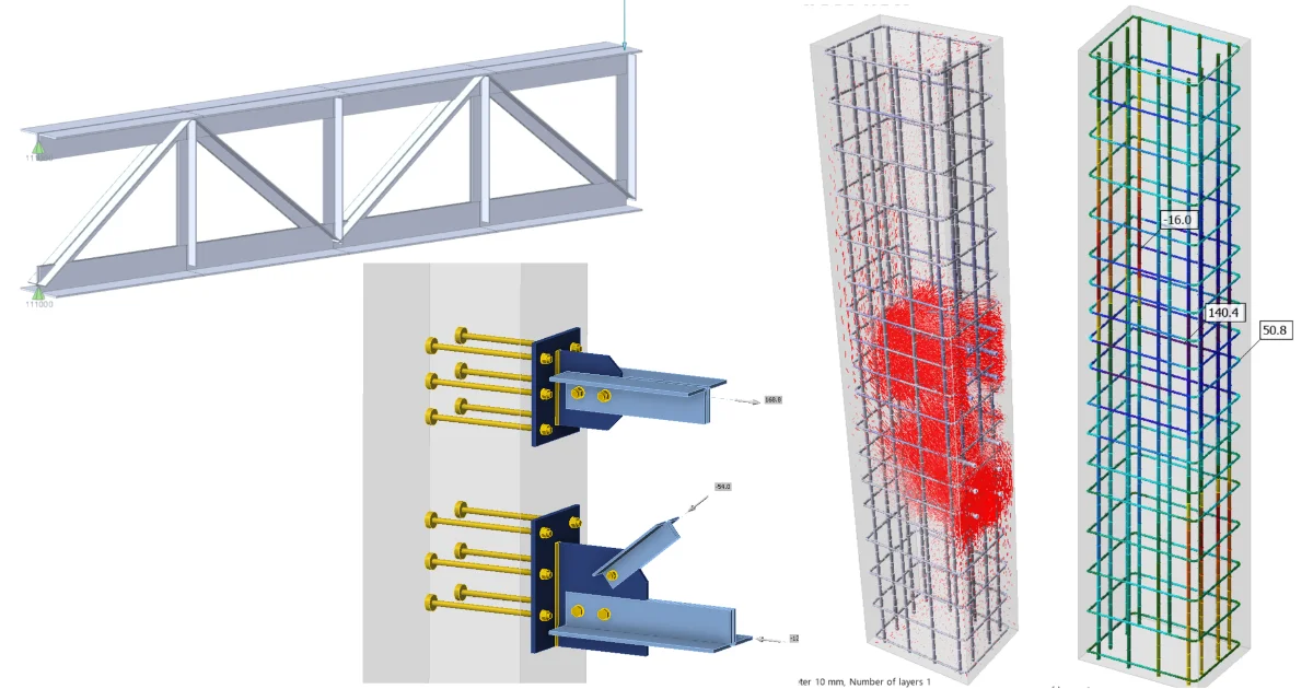
Please note that this real-world design uses optimized geometry that may trigger standard EN detailing warnings. We retain the original parameters for authenticity. See the figure below.

If you wish to skip the Connection design and proceed directly to the Detail 3D analysis, download the Detail 3D file and continue to Chapter 5.
1 New project
Run IDEA StatiCa Connection. Everything starts on the Steel tab.

Adjust the default settings for Materials, then click Create a blank design.

2 Design
After creating a blank design, change the Cross-section of a member to UB 610 x 305 x 238.

Now, add another manufacturing operation and select the Base plate.

Continue with the next Operation and choose a Fastener grid or Contact to produce a Headed studs.

Add another Fastener grid or Contact to produce reinforcement anchors.

Change the rotation of reinforcement in operation GRD2 by selecting Editor.

Add a stiffening plate.

Weld the stiffening plate to the base plate using the General weld or contact operation.

Add the operation Cut of member.

Add the last operation in the Connection, Fastener grid, or Contact.

Let's change the parameter Forces in to set the position of the hinge.

Input the internal forces for anchoring.
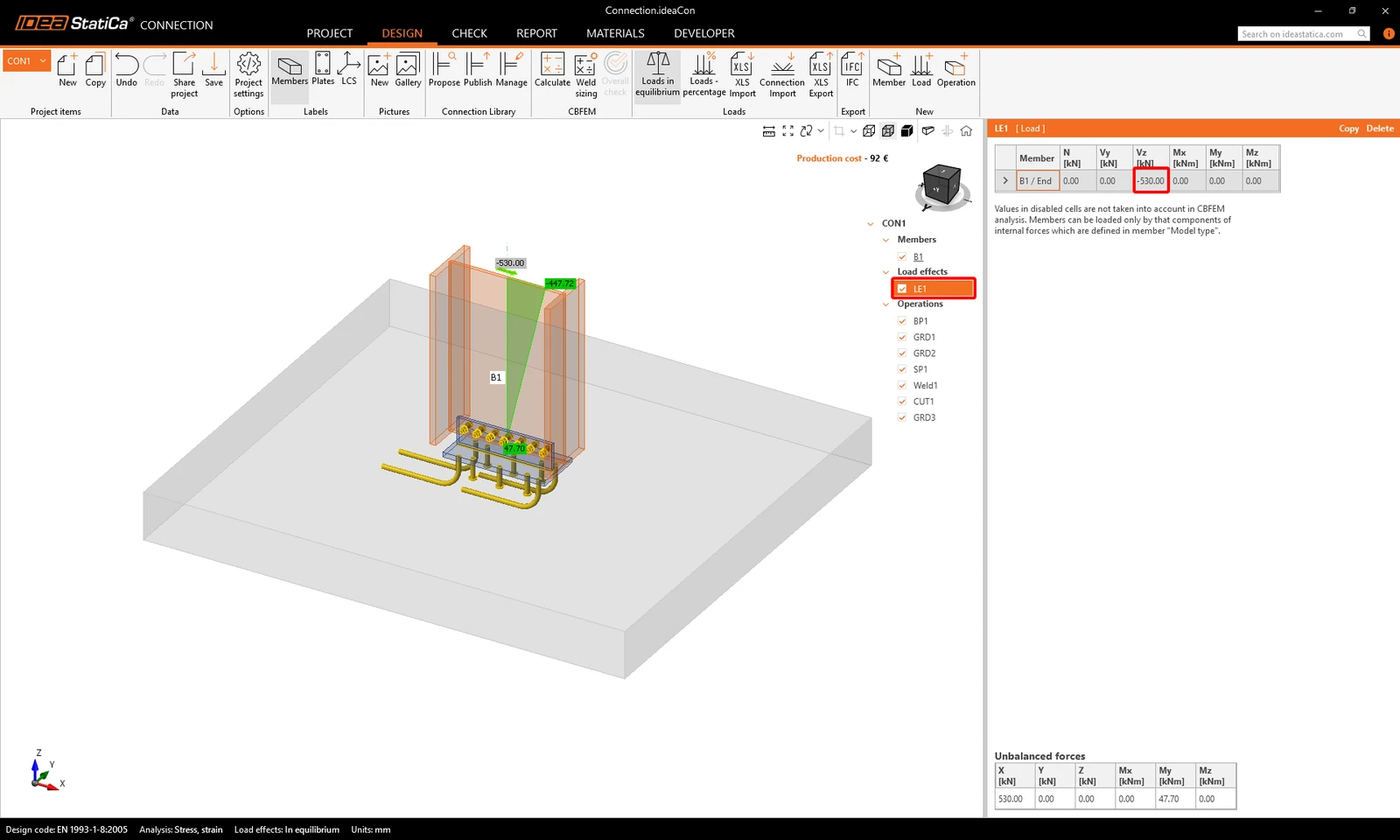
- Note: We will use only shear loading for this beam design. To simplify the tutorial, the Tying Force from the ULS Accidental combination, which was considered in the real project, has been excluded.
3 Check
Switch to card, Check -> Calculate. The code check proves the failure mode on the anchors. By default, the concrete block is assumed to be cracked.
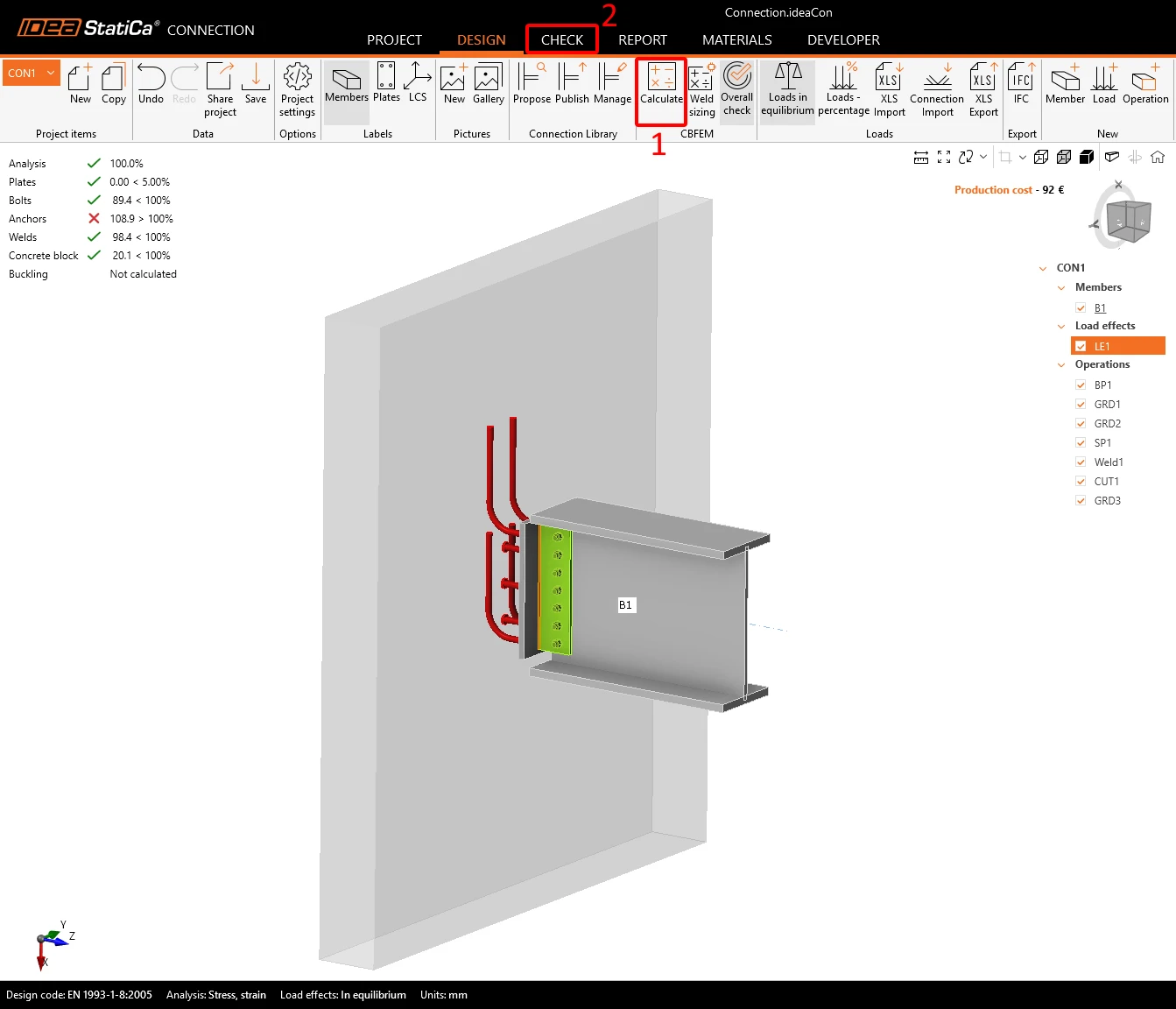
Let's explore the results. Select Equivalent stress, Bolt force, Mesh, Deformed, and Anchors. Generally, the table shows which anchors are approved and which are not.
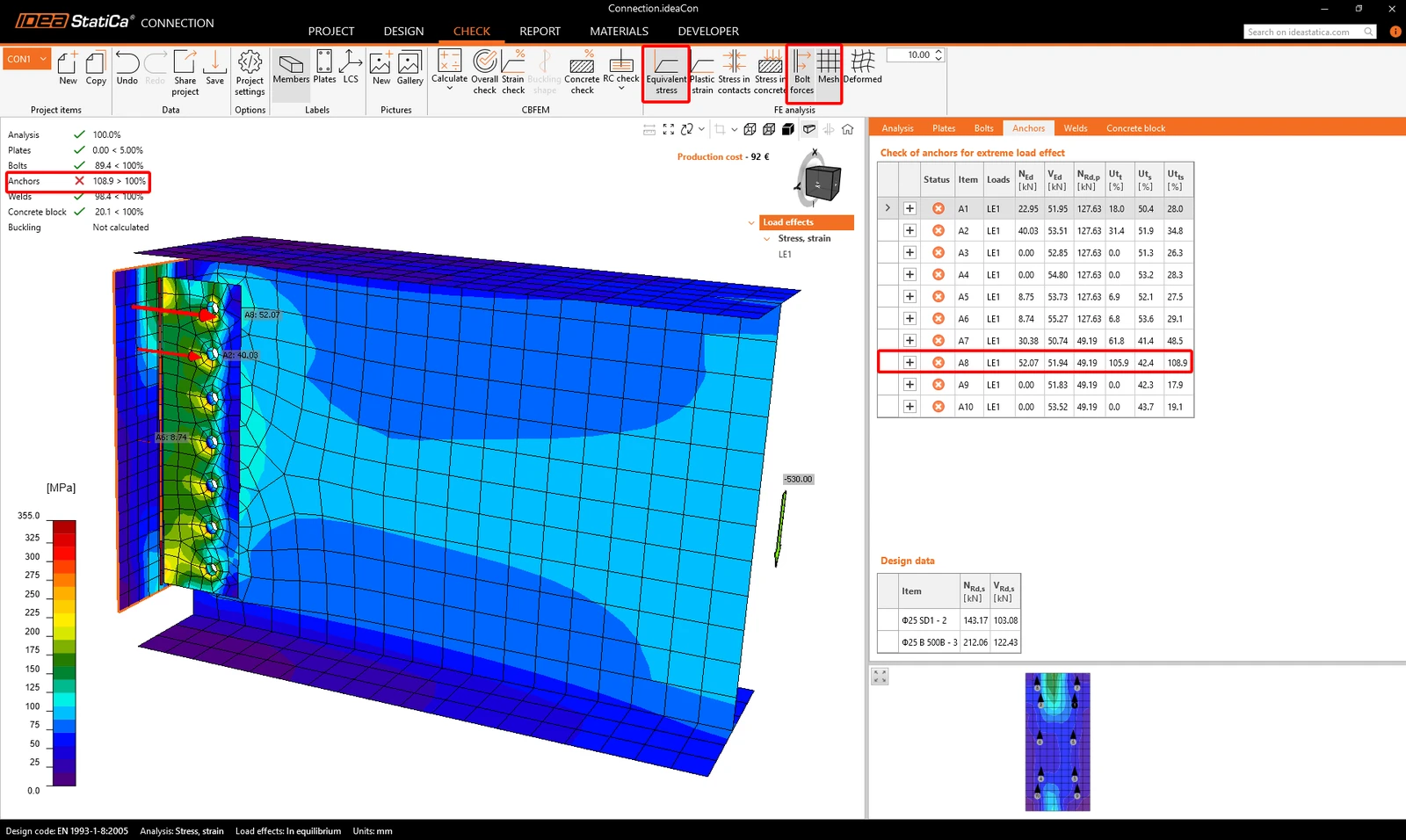
Now, let's review the details of the failing anchors to identify which code checks are satisfactory and which are unsatisfactory.
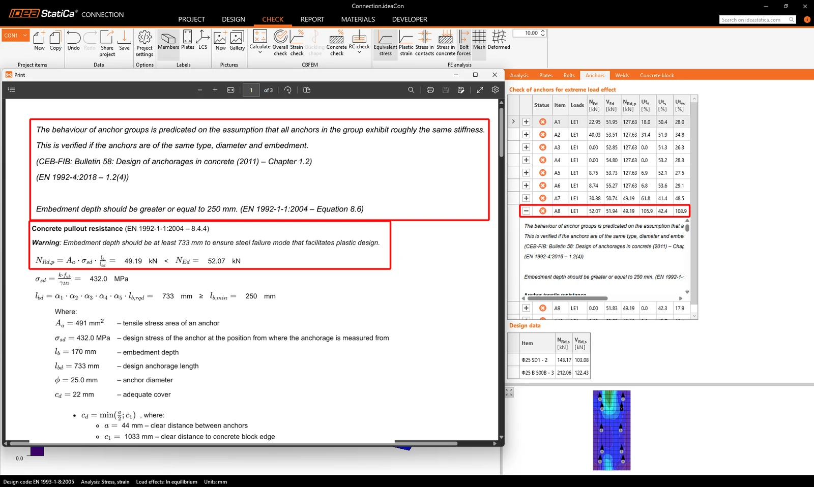
Reason for Anchor Check Failure:
- According to EN 1992-4, Cl. 1.2(4), the design of anchor groups containing different anchor types is outside the scope of the standard. Consequently, the code-check fails by default. To verify this configuration properly, a detailed analysis using the 3D Detail module is required.
Supplementary reinforcement (EN 1992-4 – 7.2.1.9; 7.2.2.6):
- The analytical code-check fails for the concrete cone, requiring supplementary reinforcement to transfer the full tension (356.3 kN) and shear (400.0 kN) loads. This is critical due to the "mixed" anchor configuration.
- This limitation can be easily resolved in Detail 3D to confirm the reinforcement efficiency. If checking manually, assume zero concrete capacity and ensure the reinforcement area covers the total reported forces.
Embedment depth (EN 1992-1-1 – Equation 8.6)
- The warning regarding insufficient embedment depth appears because this tutorial represents a real-world example with a thin wall and shallow anchors. The design's structural integrity is proven further in the Detail app.
4 Export
Prerequisites for export:
- The model must be calculated, and the results included.
Go to the card Check -> RC check -> Save.
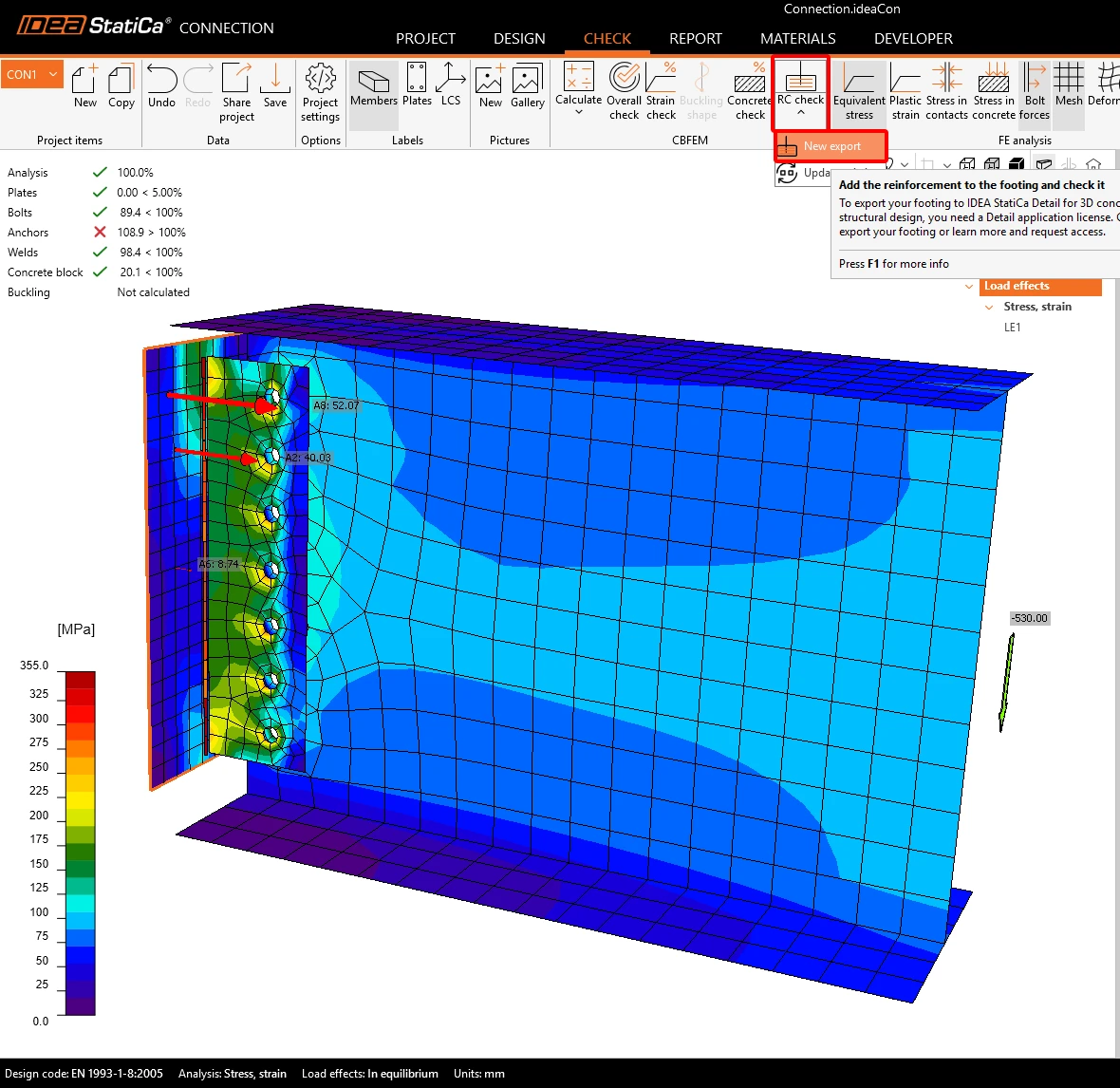
The export is allowed only for the anchoring topology. The export allows the transfer of:
- The concrete block
- Anchors
- The base plate
- Loads
Additional information and parameters that are set according to the corresponding settings in the Connection:
- Shear transfer (through Anchors, Shear lugs, and Friction)
- Material
- Anchorage Type: Post installed (Adhesive) / Cast-in place
- Anchorage type at the end: Washer/ Straight/ Hook/ Headed stud
- Friction coefficient
5 Design
This section will allow you to modify Members, Supports, Loads & Combinations, and add a Rebar assembly.
Support
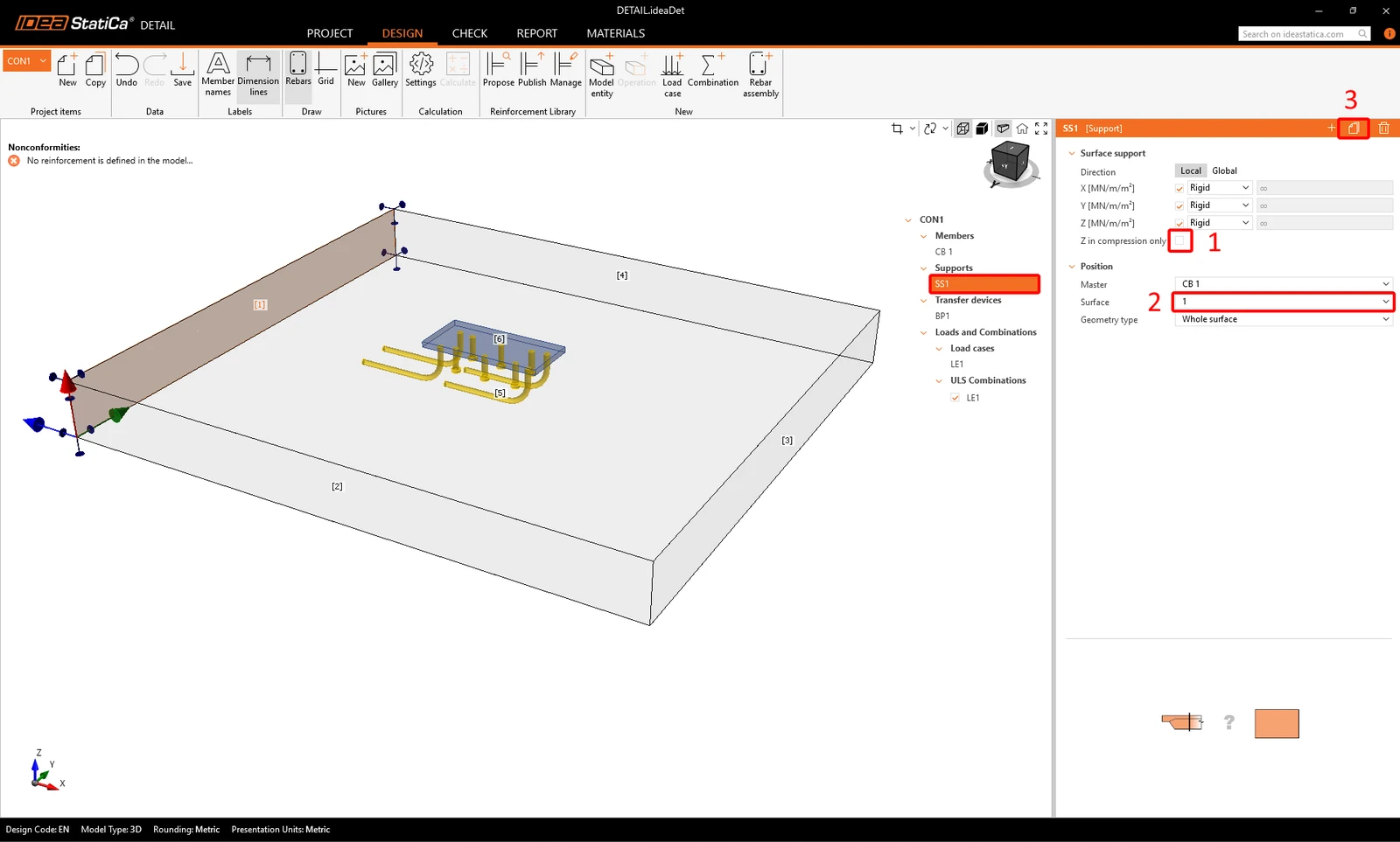
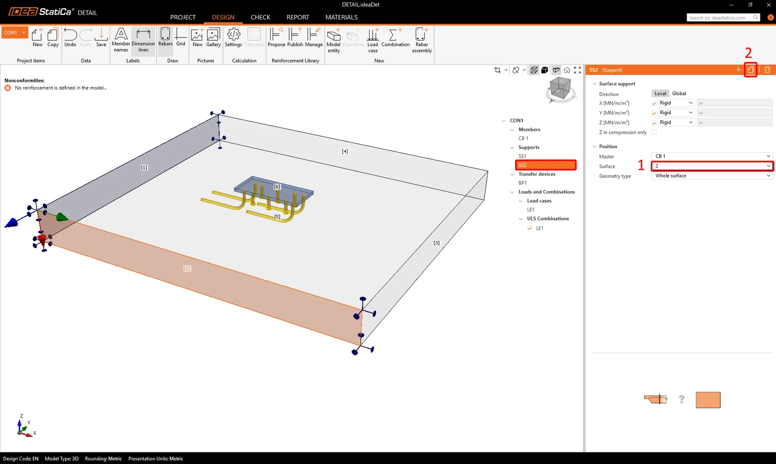
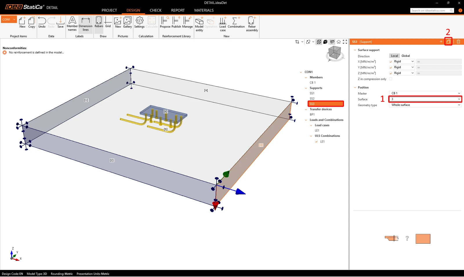
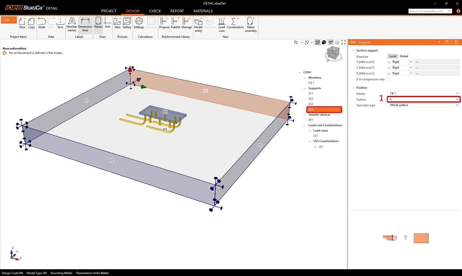
In this example, the connection is anchored to a wall that is continuous on all sides. For such submodels, we use rigid supports with continuous reinforcement. This setup simulates the wall's continuity, allowing tension transfer despite the compression-only settings, without requiring complex stiffness definitions.
Let's apply the supports to the model:
Transfer devices
The anchors are imported from IDEA StatiCa Connection. Since the design uses two different anchor types, we will separate the load transfer to ensure a safe and predictable behavior. This approach aligns with standard UK engineering practice to resolve the limitation of EN 1992-4 (Cl. 1.2(4)), which excludes mixed anchor groups from the standard scope. By assigning shear and tension to specific anchor groups, we create a verified load path compliant with safety requirements.
Anchors SF1 – SF6: Enable Active for shear transfer and disable Active for axial forces transfer.

Reinforcement anchors SF7 – SF10: Do the opposite – disable Active for shear transfer and enable Active for axial forces transfer

If you were designing a footing from scratch in the Detail application, both options would be enabled by default. When transferring shear, you must determine which anchors will resist the force and select them accordingly. This aligns with EN requirements, which specify that shear should only be assigned to anchors effective for the concrete edge failure check.
Reinforcements
Let's increase the height and width of the concrete block. This provides a clearer view of the model and allows us to observe the complete stress profile along the rebars.

Set the Concrete cover to 30 mm; this will serve as the default value for the reinforcement. Additionally, set the default Anchorage type for longitudinal bars and stirrups.

Before defining the reinforcement, deactivate the Rebars button. This ensures that only the specific bar group you are currently selecting is visible, keeping the view clean and uncluttered.

Next, insert a new On Surface reinforcement to create the continuous longitudinal horizontal reinforcement (main reinforcement at both surfaces).
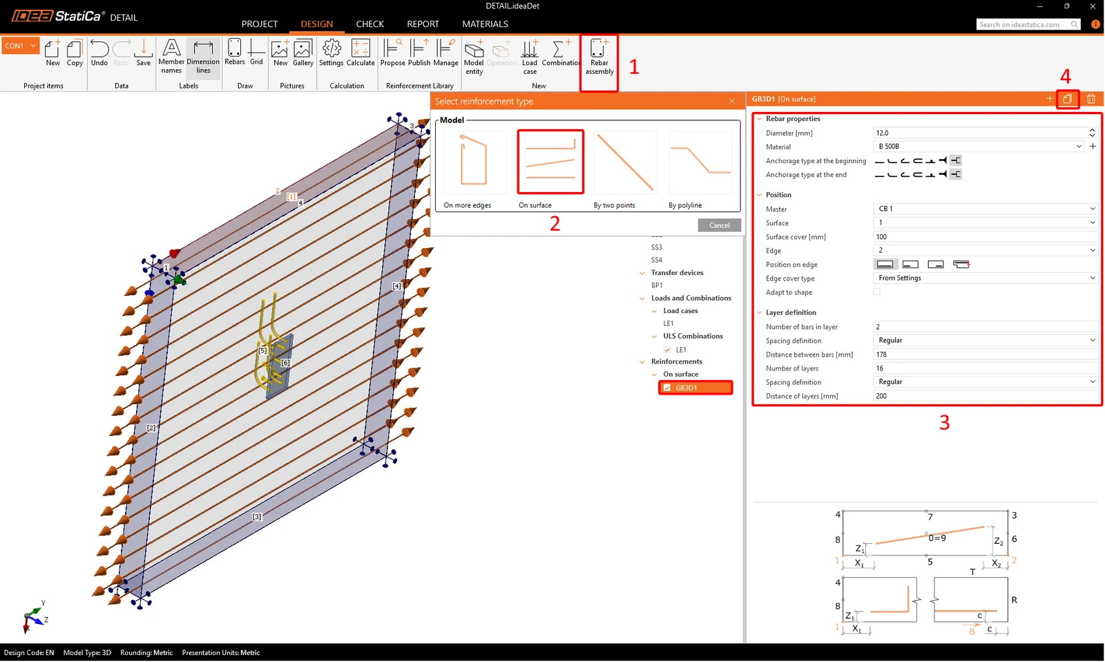
Duplicate the operation to add the continuous vertical reinforcement at both surfaces and adjust the settings as shown below.
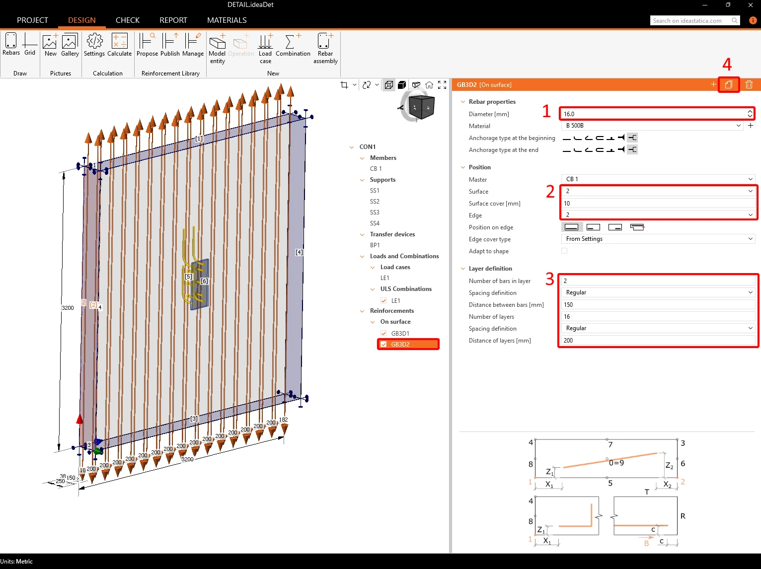
According to the structural calculations, additional shear reinforcement is not required outside of the shear perimeter. Therefore, the following steps focus solely on creating the shear reinforcement within the shear perimeter based on the original design.
Copy the existing reinforcement item and edit it accordingly to get appropriate links representing the shear reinforcement.
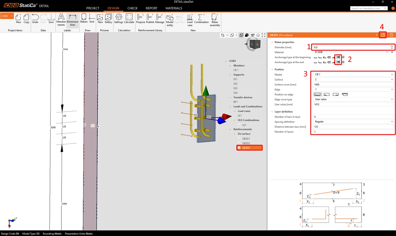
Duplicate operation GB3D3 and update the options below to define the shear reinforcement.
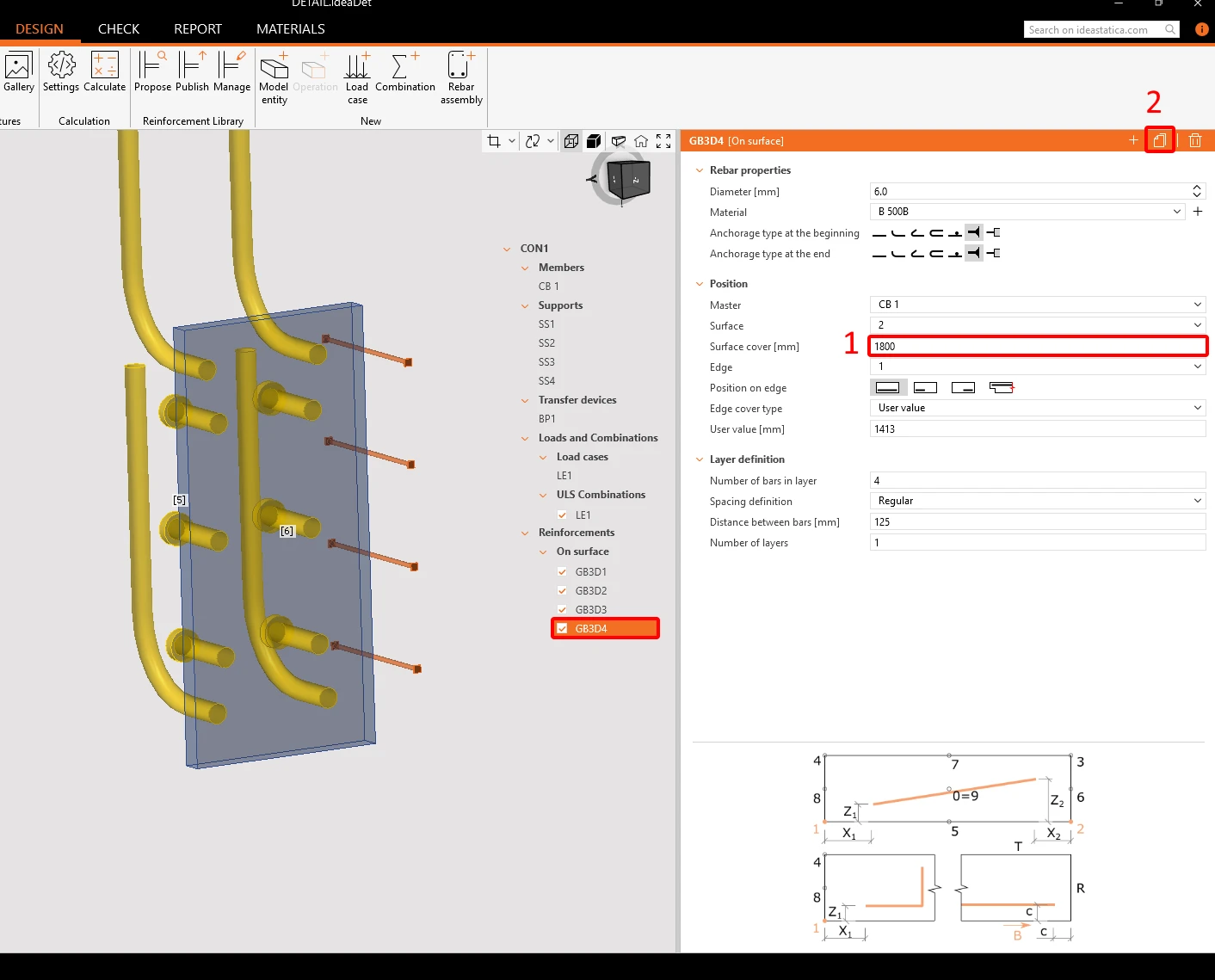
Proceed by copying operation GB3D4 and changing the parameters.
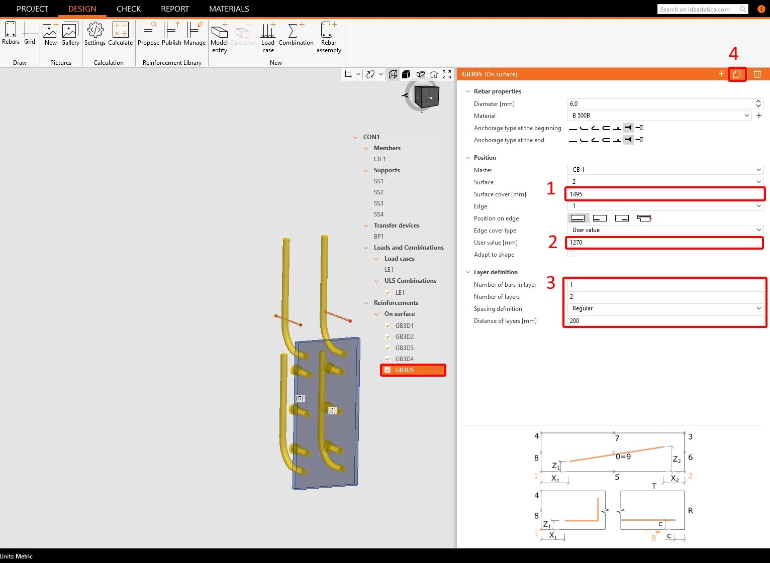
Now, copy operation GB3D5 and modify its settings to meet the shear perimeter requirements.
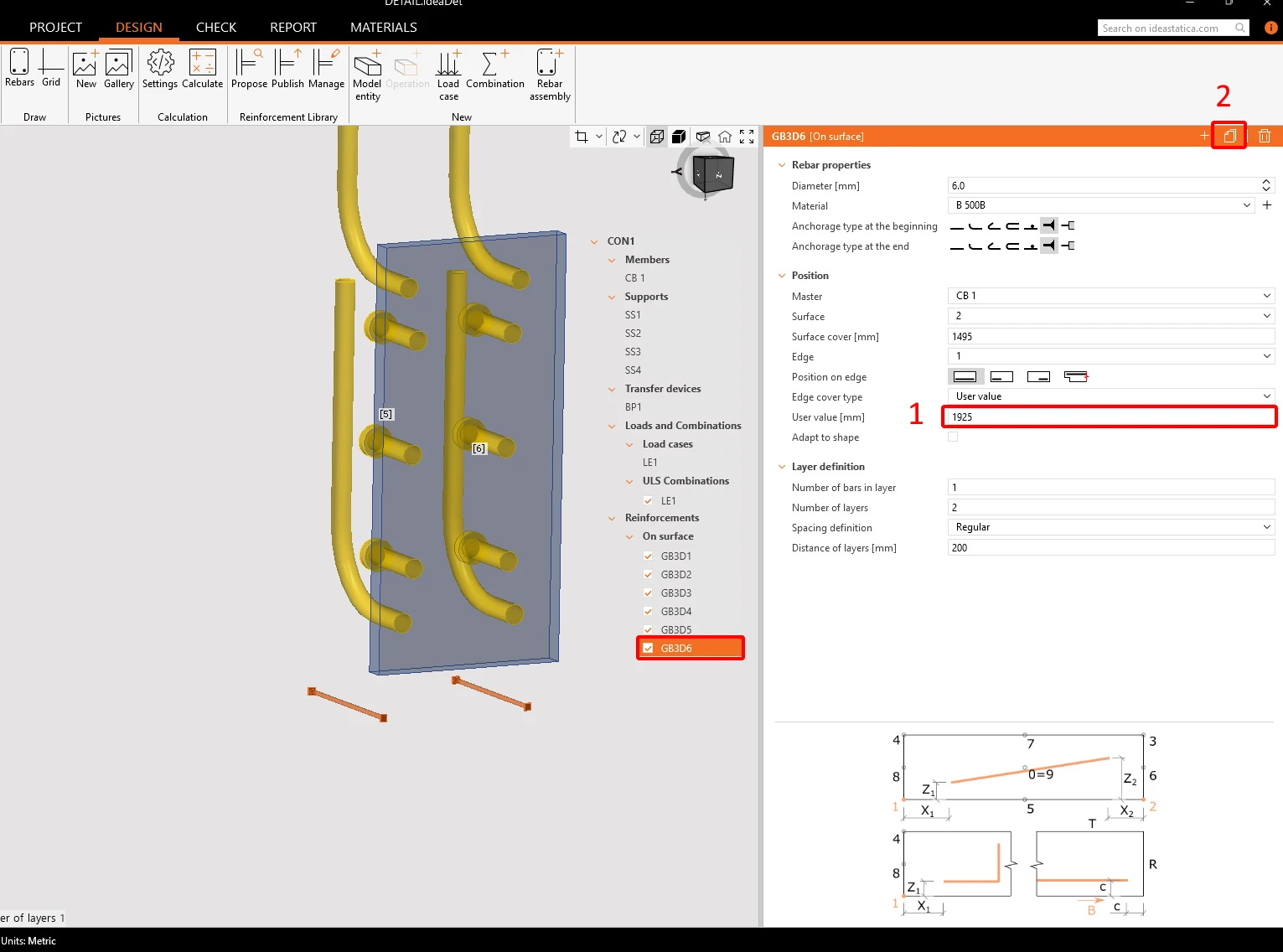
Reuse operation GB3D3 by copying it and adjusting the values.
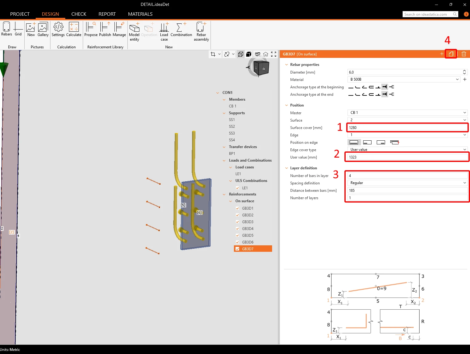
Copy operation GB3D7 and change the options.
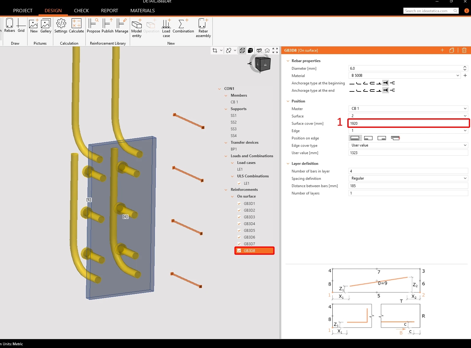
Create another copy of operation GB3D5 and apply the changes below.
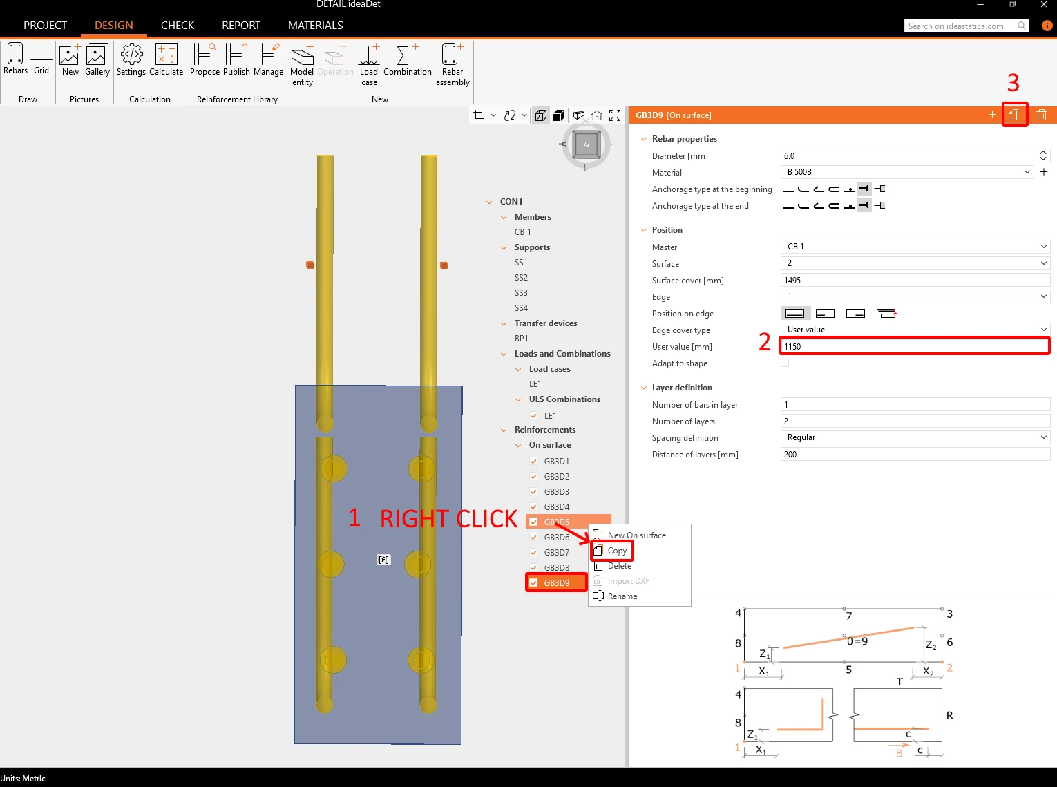
Finally, copy operation GB3D9 and update the final reinforcement options.
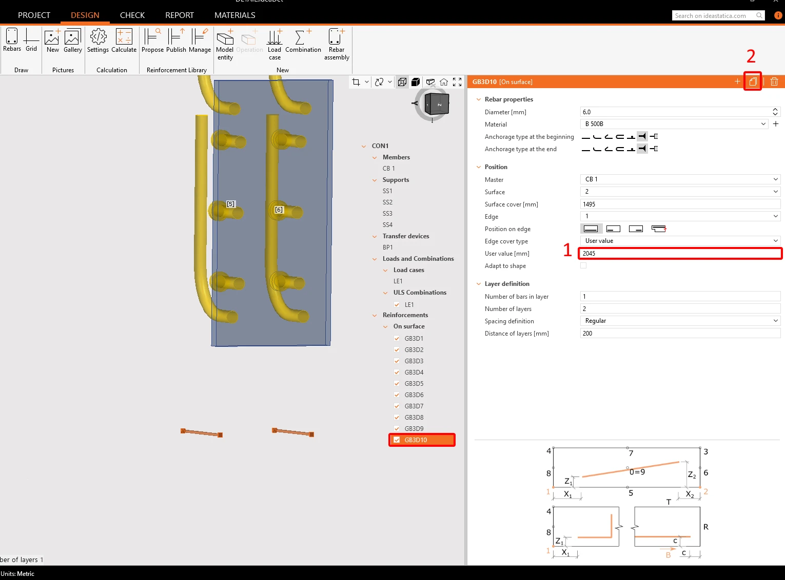
Now, let's define the constructive shear reinforcement. Although it is not required by the structural calculation—since the concrete alone passes the shear capacity check in this specific case-we still need to comply with the standard detailing rules. Furthermore, IDEA StatiCa Detail requires the model to accurately reflect the real-world reinforcement layout.
The irregular spacing helps to organize the links systematically.
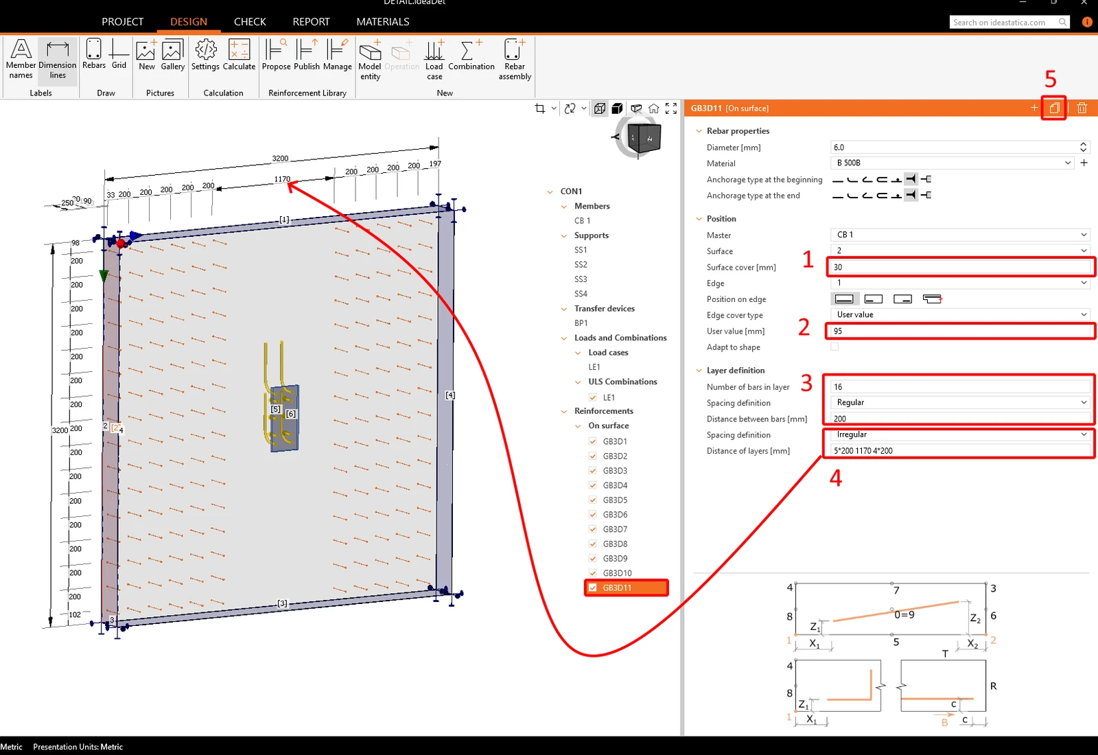
- Note: From a computational perspective, defining this reinforcement in the Detail application is essential. As stated in the Theoretical background of the CSFM method, and also mentioned in Kaufmann's book on CSFM.
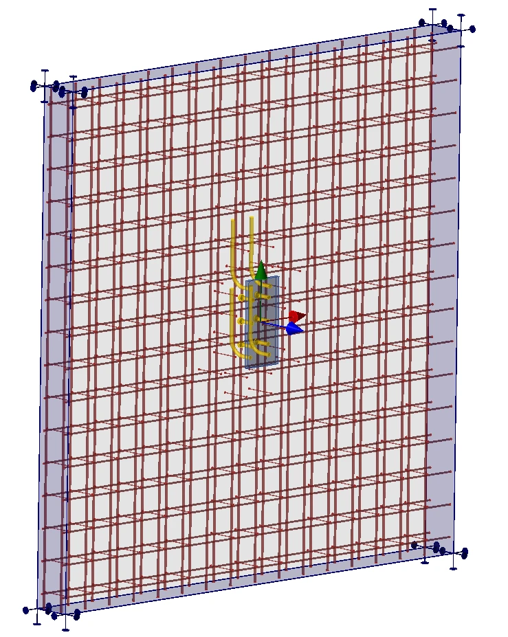
Copy operation GB3D11 and change the options.
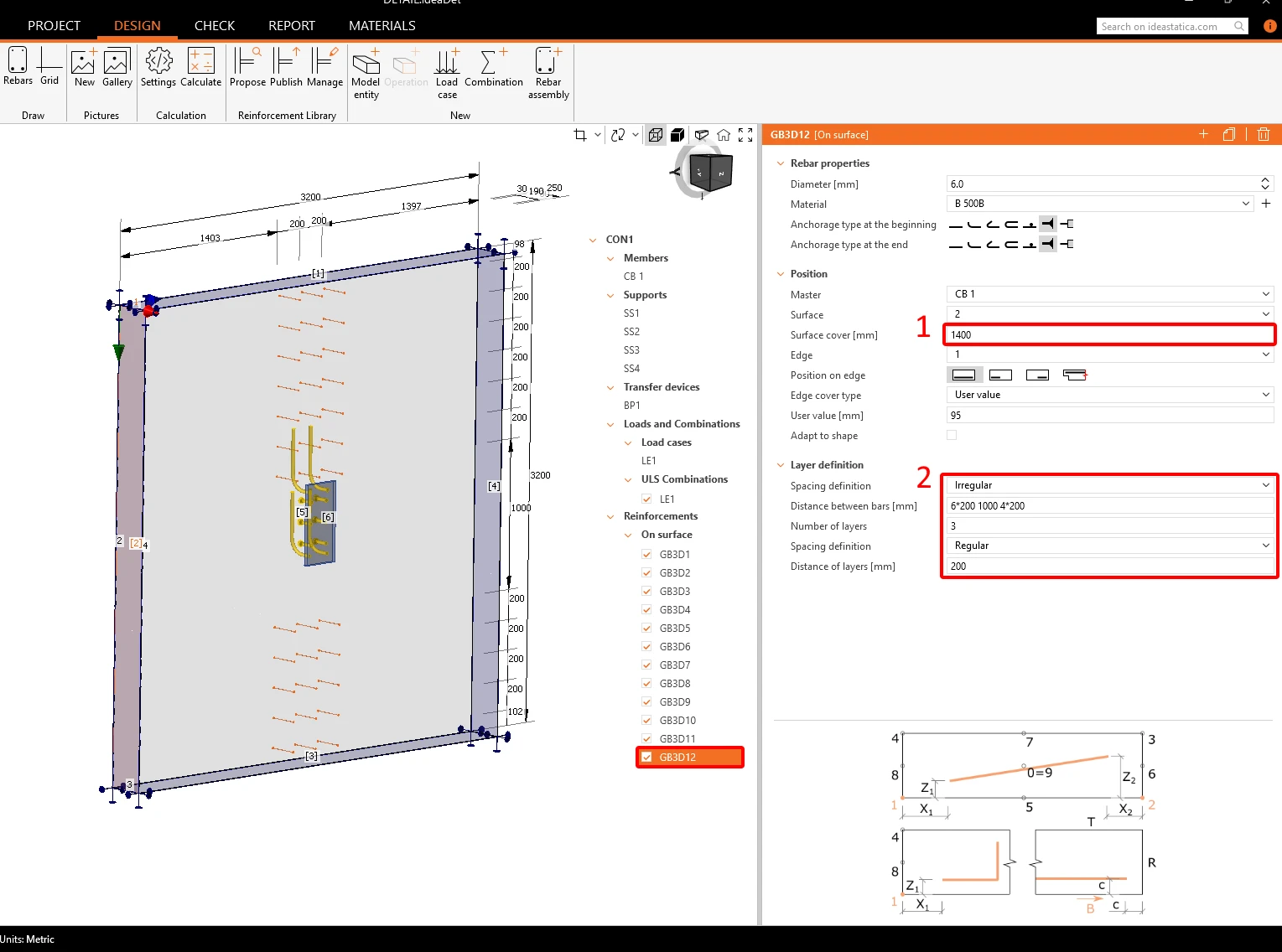
Ultimate reinforcement design.
Loads and combinations
Combinations are taken over from IDEA StatiCa Connection. All the consequences of import are mentioned
in this article.
Let's add the Self-weight:

Create a combination with Self-weight, and add the coefficient for self-weight = 1.35 according to the code
EN 1991-1-1

6 Check
Before running the analysis, we highly recommend changing the Mesh multiplier to 2 or 3 to speed up the calculation. While this step is not mandatory, it significantly reduces computational time and helps detect potential divergence issues early. If the analysis runs smoothly, you can then revert the Mesh multiplier to 1 for the final results.

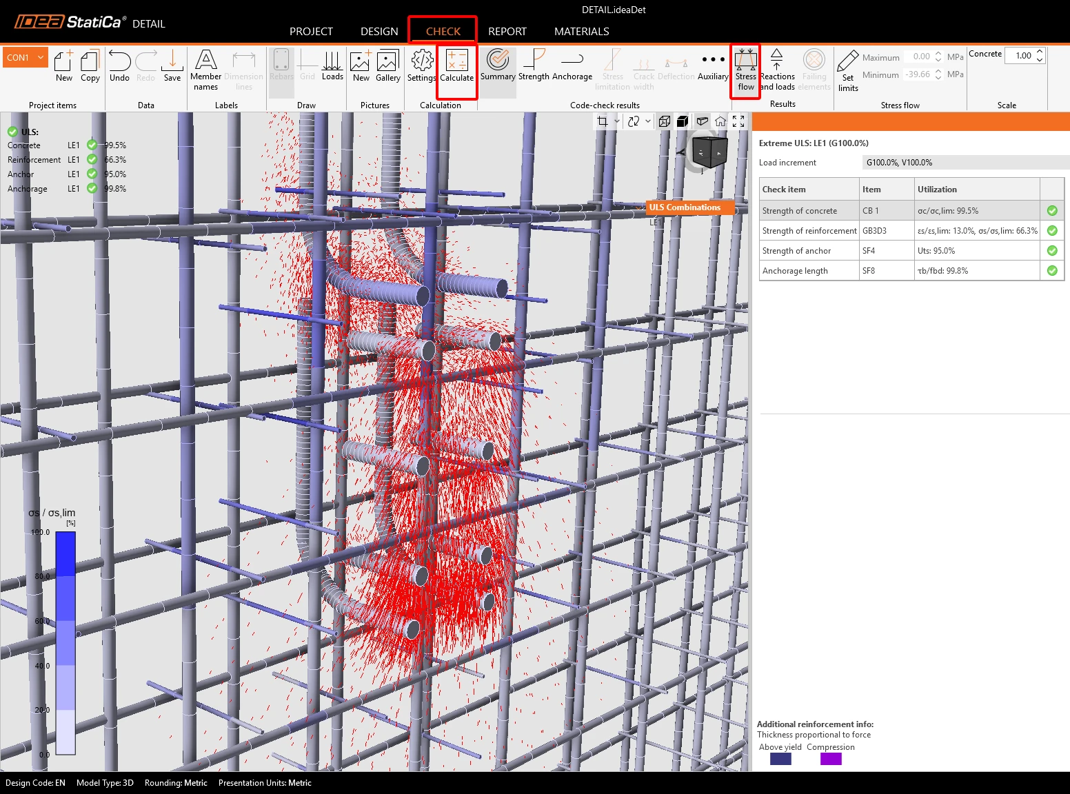
Distribution of principal stresses in the compression within the volume of concrete.
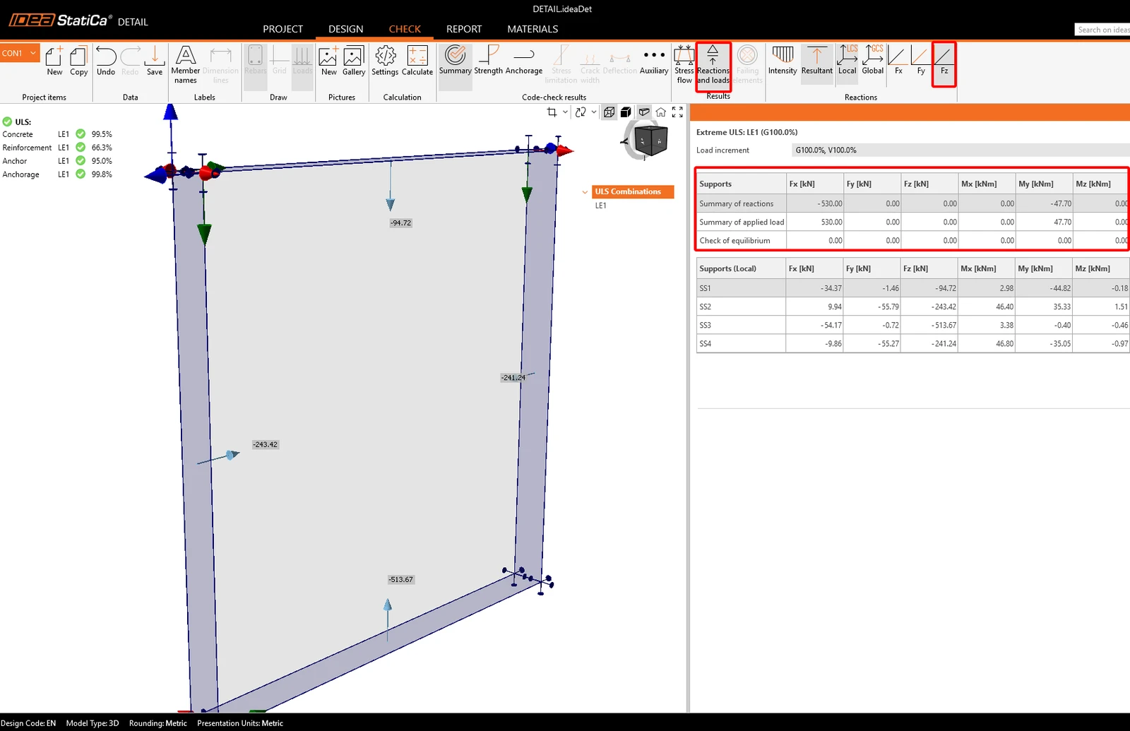
The support reactions and static equilibrium between external loads and reactions. The ideal scenario is to achieve absolute zero in the "Check equilibrium" code check, which guarantees full transfer of forces. Small residuals, such as 1 kN and 1 kNm, can be numerical artifacts.
Results
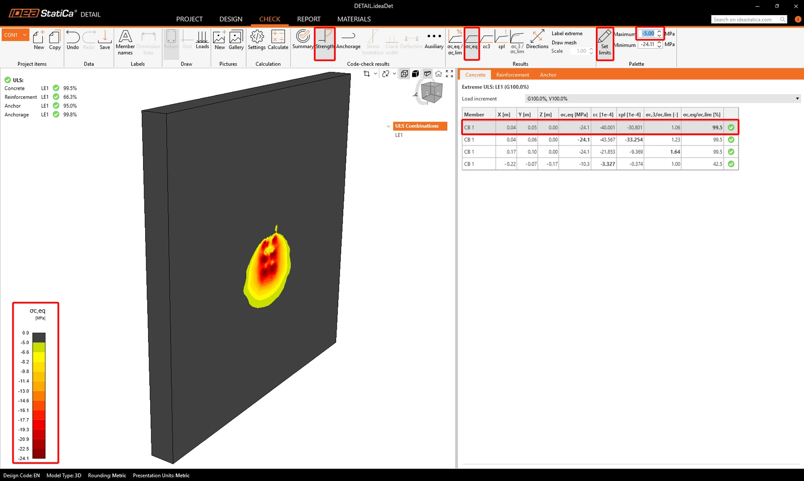
Equivalent Principal Stress
The equivalent principal stress (EPS) in concrete is determined based on the triaxial behaviour of the concrete block. The areas experiencing the highest loads are identified and highlighted. To provide insight into the effect of confinement compared to uniaxial compression, the equivalent stress is calculated using the kappa factor.
The range of the stresses is scalable using the range function. It reveals the area affected by those stress ranges and gives you insight into how the stress is concentrated on the detail itself.
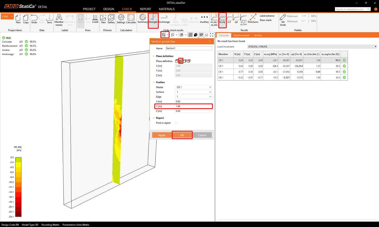
Result section cut
To inspect the internal behavior of the concrete block. Use the + New button to create Sections and adjust their Plane definition (position and rotation) in the properties window to cut through critical areas. This highlights where the concrete undergoes plastic deformation. You can save these views to the Gallery for your final Report. More information is available in this article.
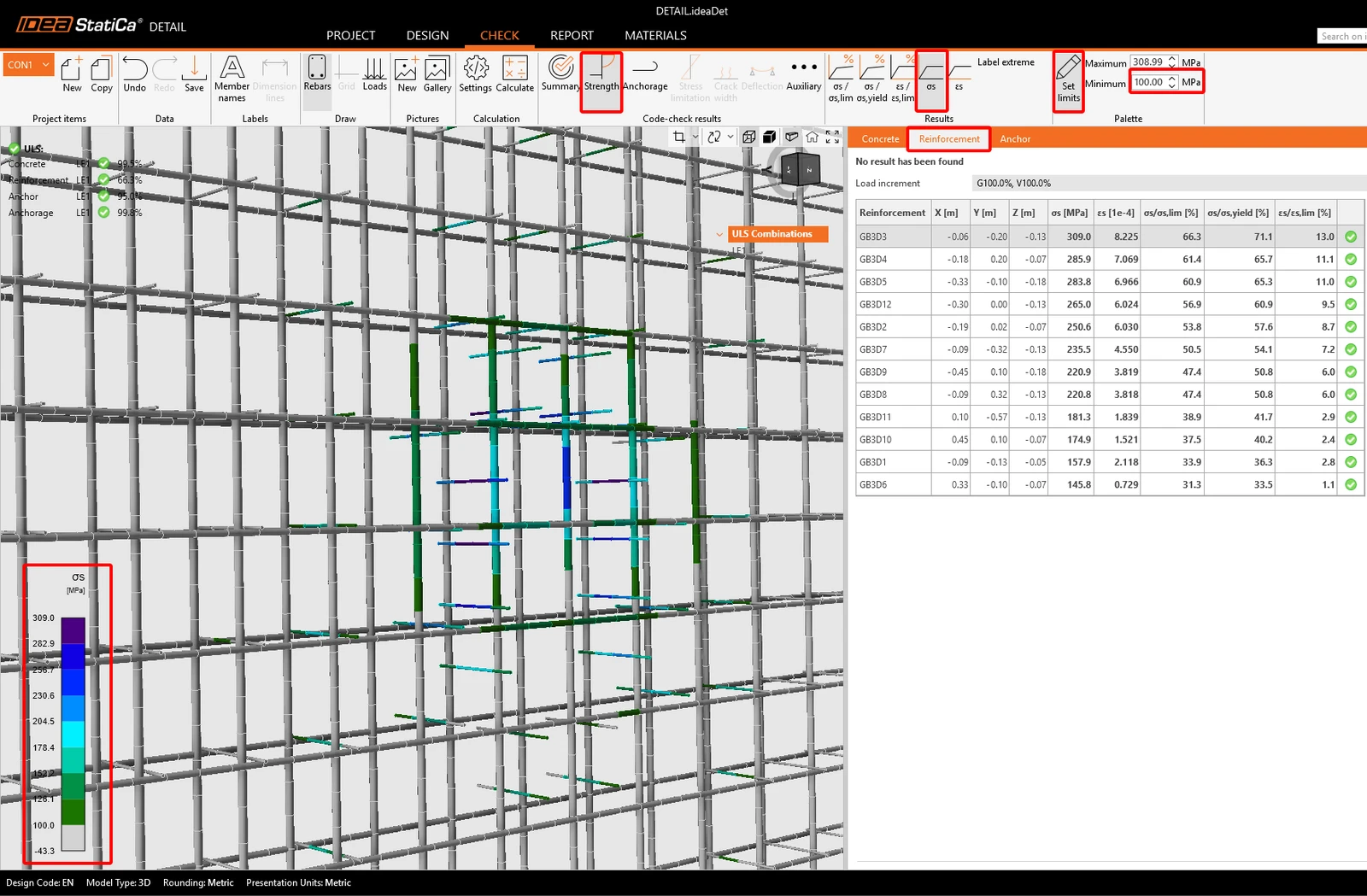
Stress in rebars
The results identify the stress on rebars. Detailed values for stress, strain, and utilization for all bar groups are listed in the Reinforcement tab.
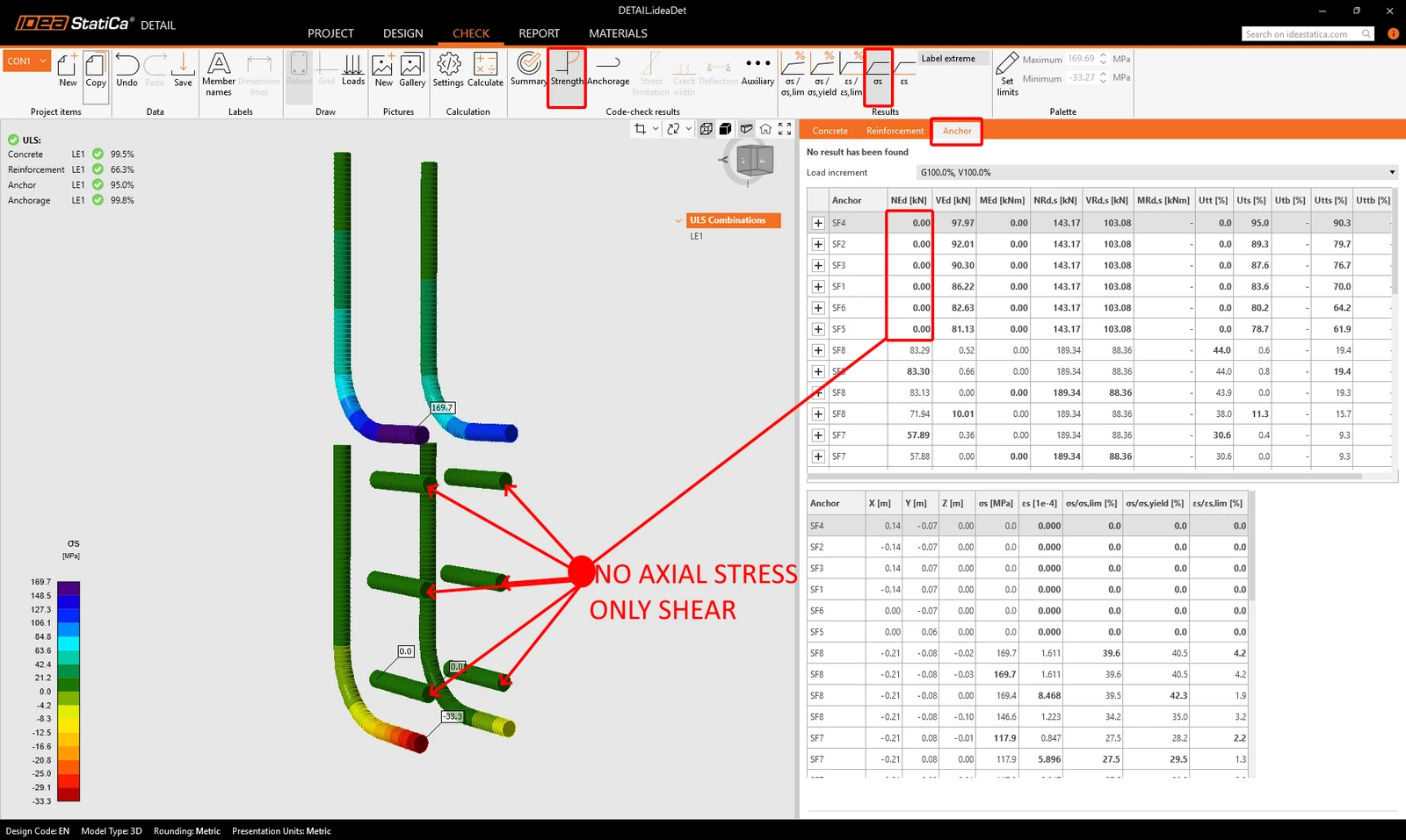
The anchor check card provides insight into the behavior of the anchors from the perspectives of stress, strain, and force transfer. Here is proof that the anchors SF1-SF6 are deactivated in tension and carry only shear. The remaining set of anchors, SF7-SF10, on the other hand hand, carry the load only in tension.
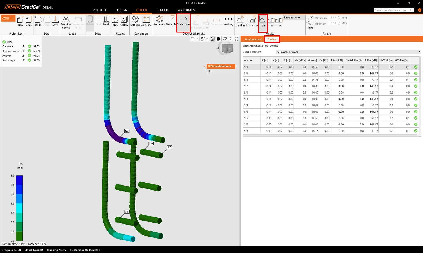
Anchorage
The Anchorage tab verifies the bond strength between the reinforcement and concrete. It ensures that the provided anchorage length is sufficient to transfer the forces. The check compares the actual bond stress (τb) with the ultimate bond strength (fbd) to prevent pull-out failure. You can display these results separately for Reinforcement and Anchors.
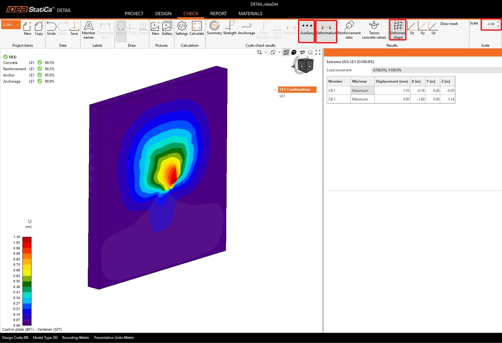
Deformations
Switch to the Auxiliary tab and turn on Deformation. Although deformation limits are not prescribed for ULS (Ultimate Limit State), reviewing the deformed shape is a crucial sanity check. It ensures that the model is stable and not experiencing unrealistic displacements or rotations (e.g., due to disconnected elements). This visual inspection helps quickly identify any potential modeling issues.
7 Report
Finally, go to Report -> Detailed -> Generate. IDEA StatiCa offers a fully customizable report to print out or save in an editable format.

You have performed a complete design check according to EN 1993-1-8 (steel joints), EN 1992-4 (anchors), and EN 1992-1-1 (concrete structures). The steel joint and anchorage were verified in IDEA StatiCa Connection, while the concrete block integrity and reinforcement were analyzed in IDEA StatiCa Detail using the CSFM method compliant with EN 1992-1-1.