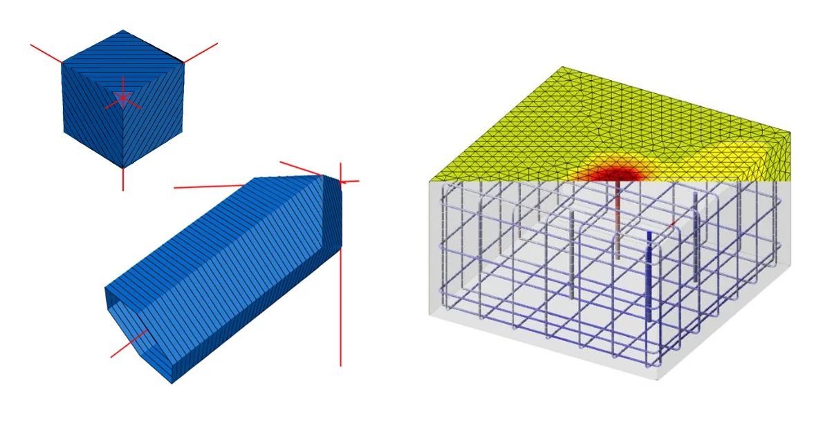
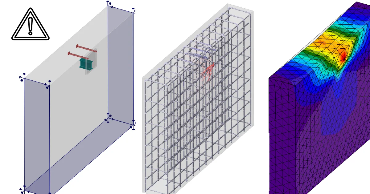
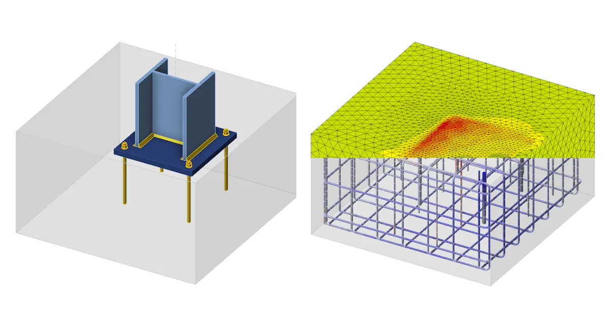
In the following article, we will first explain the basic principles of modeling, and later show advanced options suitable for complex examples and atypical shapes.
- Basic Principles
- Advanced Options
Basic Principles
Four Reinforcement Entities
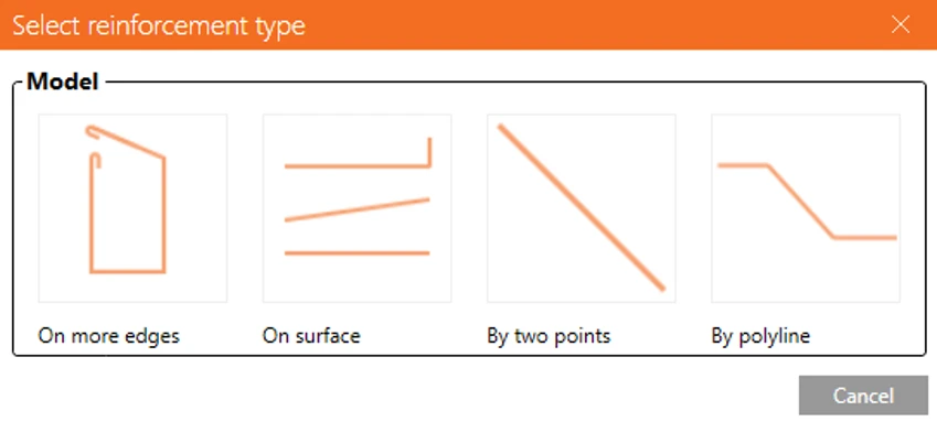
Reinforcement is created through the Rebar assembly command, which offers four separate entities:
- On more edges — places reinforcement along a list of edges or surfaces
- On surface — positions rebars relative to a single reference surface and edge
- By two points — defines a bar directly between two coordinates
- On polyline — defines a bar shape from a list of points
The basic principle of placing reinforcement for both the On more edges and On surface options is that you first need to select a master (reference) element, and then choose the appropriate reference surfaces and edges based on the master element's numbering — see example.
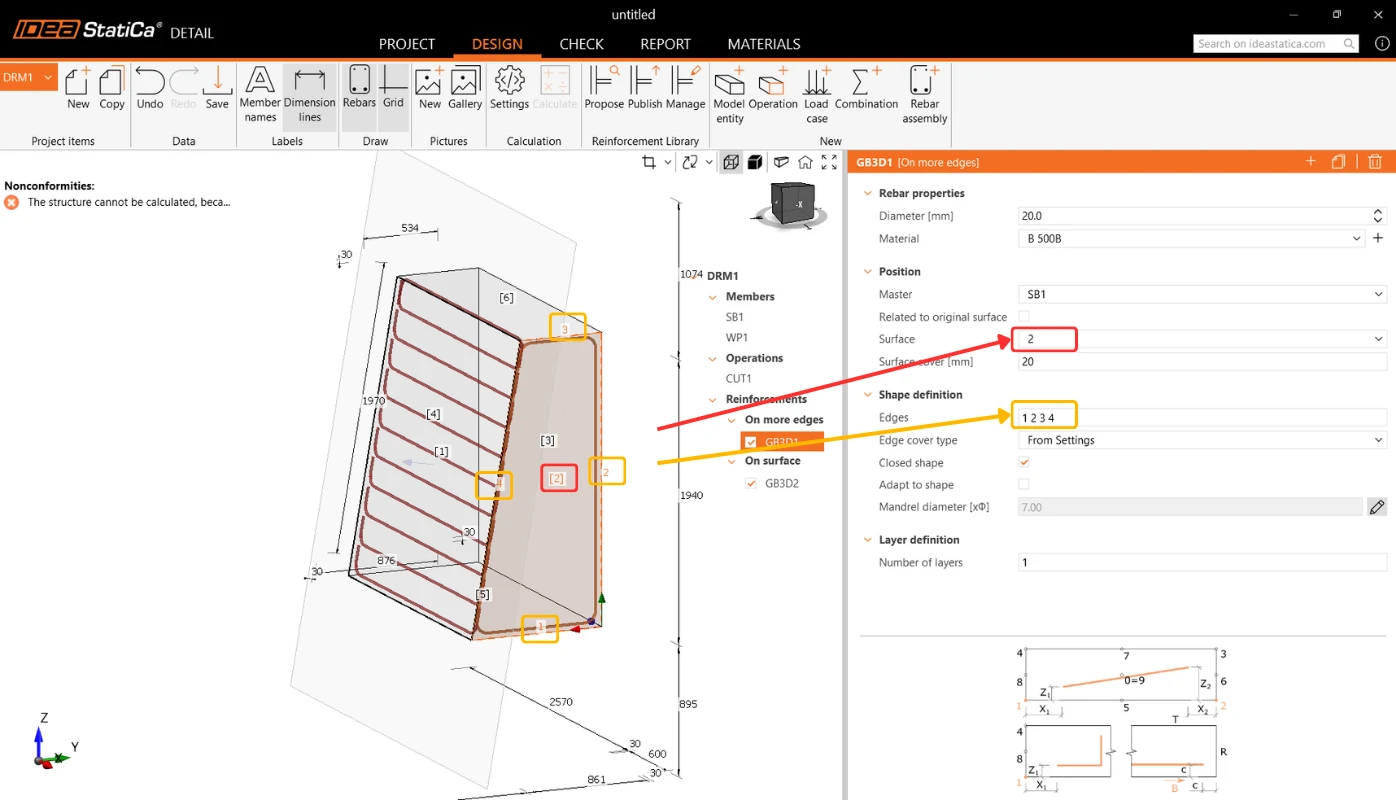
Beyond that, each type has some shared property settings available, such as bar spacing, anchorage type, and others, as well as some settings unique to that specific definition — for example, the On more edges entity can be set as closed, and so on.
The other two reinforcement entities, by contrast, are defined using coordinates or vectors.
By two points can be defined in multiple layers, replicated along a vector, referenced to master element — or in global coordinates when no relation to a model entity is wanted.
A polyline is defined using a table for entering points, including the ability to paste values directly from Excel via copy-paste. The polyline can be defined relative to a model entity — to the origin of an edge (the local coordinate system cross is drawn) or to the centre of a face — or in global coordinates.
Advanced Options
Reinforcement Reference Geometry
In addition to a solid block, the Master for a reinforcement entity can also be assigned as a negative volume or a working plane.
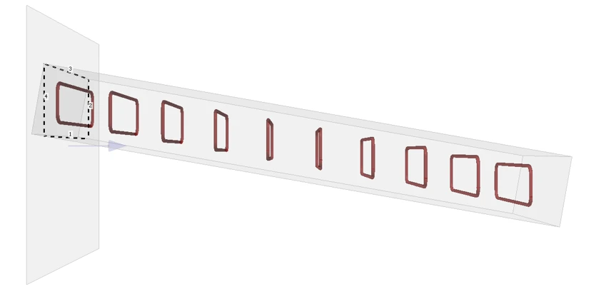
- Working plane — a general section through the body, defined either by a normal vector or by three rotation angles. Basic reinforcement shapes are defined in the plane, which is far easier than working directly with complex 3D geometry.
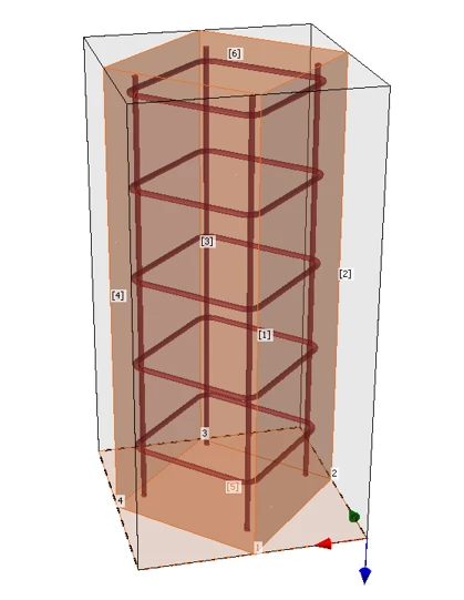
- Negative volume — can be placed anywhere in the body, can be even rotated, with reinforcement built directly into it.
Closed Shape for Stirrups
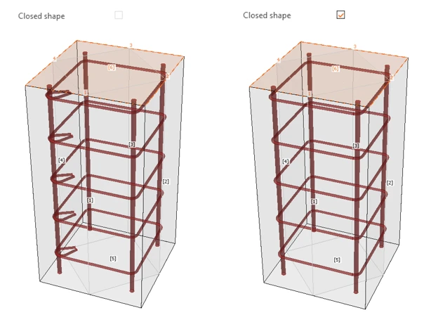
The Closed shape property connects the first and last points of the reinforcement shape into a continuous bar. Anchorage type settings are disabled, and the scene shows a closed stirrup without hooks. Because the stirrup is modeled continuously instead of being terminated by anchorage springs, the artificial discontinuity is gone – and so are the result peaks it caused.
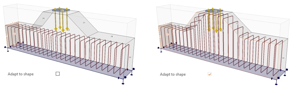
Reinforcement Adapts to the Shape of the Block
The Adapt to shape option controls this behavior: when active, the individual bars in a layer adjust to follow the shape of the referenced solid or negative volume; when inactive, all bars keep the shape defined on the input surface. Both behaviors are supported as legitimate design intents, and the applicable mode is selected explicitly rather than fixed by the tool.
Regular and Irregular Spacing
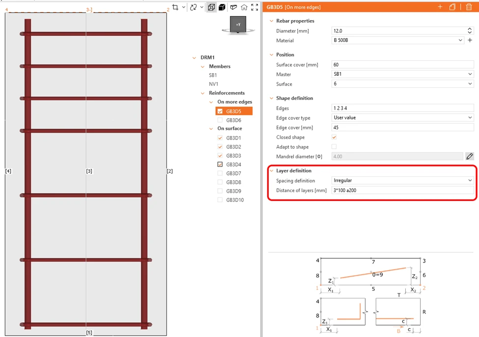
Layer spacing has two options for Spacing definition:
- Regular takes a single distance value
- Irregular accepts a list of distances — so a non-uniform layout is entered directly instead of being split into several entities.
Reinforcement that extends beyond the block is trimmed automatically, regardless of which Master type was used.
Note: Advanced reinforcement design options were released in IDEA StatiCa version 26.1.