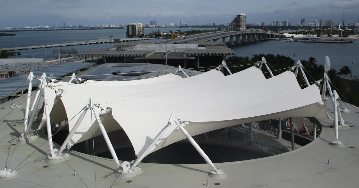


After years of designing "normal" steel structures — warehouses, frames, halls full of repeating logic — you suddenly find yourself staring at a mast tilted in space, cables pulling from directions your intuition doesn't immediately like, and connections that look more like mechanical sculptures than structural details. That's exactly what we got into during a recent webinar on membrane structures and their steel connections, together with ixRay, the company behind the ixCube 4-10 software.
At first glance, it felt familiar. A global model, a couple of load cases, and a basic drawing of the details. But as soon as I started modeling the nodes, things got interesting.

Global analysis is the easy part
The workflow started the same way most of ours do. A membrane structure — masts, cables, and fabric working together — was analyzed globally in ixCube 4-10, load cases prepared, deformations checked, everything neat and tidy by Gerry. Masts, cables, and membrane all doing their thing, form-found and happy (well, it was a public webinar, right?).
Then I took over the connections.
IDEA StatiCa Checkbot still helps here. Using the BIM link, the geometry, cross-sections, and load combinations get exported straight from ixCube 4-10 into IDEA StatiCa — no manual rewriting of forces, no fighting with coordinate systems.
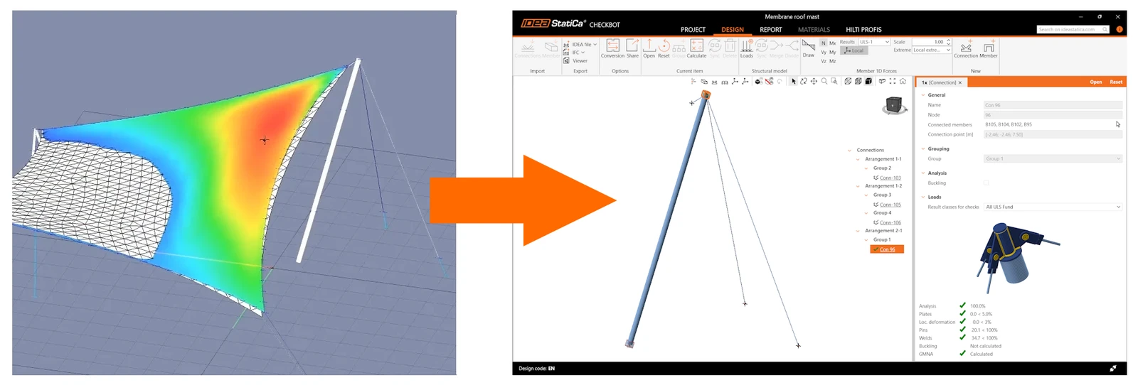
Suddenly, geometry matters. A lot
Once the nodes were imported, the difference between membrane connections and "normal" steel details became obvious immediately.
Unlike standard steel structures, where nodes repeat themselves like wallpaper patterns, here every joint was its own animal. Mast heads with cables coming in at strange angles, anchoring nodes interacting with concrete, pins here, eccentricities everywhere.
But the worst part is, this world is not orthogonal! Membrane structures are a spatial mess, no perpendicular members, plates are rarely rectangular, forces mostly axial — until they aren't, because of the angles.
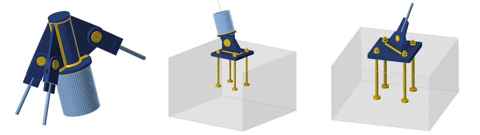
Instead of selecting a connection template and tweaking bolt numbers, the design became a sequence of the good old manual operations. What saved my a..., ehm, authority as an expert Connection app user, was importing the actual shaped gusset plates from DXF files instead of shaping them in the app.
And I stretched my brain further, especially positioning the plates in space so that they fit the member vectors. Here, the Stiffening plate operation option to set the Origin as Member LCS or Plate also really helped. After that, it was pure millimeter poker with the X and Y offsets and rotation — oddly satisfying, actually.
Alright, this took a while. But these techniques did the trick, and I was much closer to hitting the red button (that's Calculate, for anyone wondering).
Cables are not beams
But before that, a bit more tuning ahead. By default, connection models happily assume that members transfer all internal force components. Fine for beams and columns. Completely wrong for cables.
In membrane structures, cables are there to carry tension. That's it. No bending moments, no rotational stiffness, no shear. Can IDEA StatiCa Connection model cables? No. But there's a workaround — and a good one. The cable itself and its pulling mechanism are the manufacturer's problem, already certified. What matters here is the joint it pulls on. So the cable is modeled as a full rod instead, with all parameters according to the cable imported via the BIM link.
Pins are not bolt grids
Membrane structures are full of connections that are, mechanically, a single pin doing all the work. IDEA StatiCa lets you model a genuine one-pinned connection by virtually adjusting the end supports of the connected members.
Technically, you do this with one click in the member properties — switching cable members to model type N-Vy-Vz. The forces input is already pre-cooked, since only tensions are imported from the FEA global mode. In this case, releasing everything but the normal force is not a software trick to get the green ticks. It’s structural reality catching up with the model.
Skip this step, and you can end up with a connection that calculates while being a physical nonsense, or, more likely, a non-calculable mechanism with the ultimate message "analysis 0%".
Now is the time for hitting the red button — and the dopamine hit that comes with it.
This is where (CB)FEM shows off
Watching the results appear is just fun. You still get your green/red pass-fail tables required by Eurocode and a PDF report to finish your workday. But you also get stress fields flowing through oddly shaped plates, concentration zones around pin holes, deformation shapes that immediately match — or challenge — your engineering intuition.
You could clearly see which plate was really working and which one was just sunbathing.
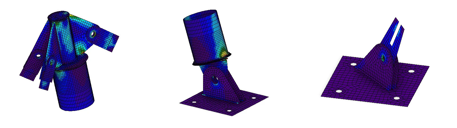
For membrane structures, this is invaluable. These are details where "it passes the equation" is simply not enough. You need to see what is happening. And yes — sometimes the governing component isn't the one you expected at all.
Final thoughts
Designing steel connections for membrane structures is demanding. It forces you to be precise, to respect real behavior, and to stop hiding behind simplified assumptions. But it's also deeply satisfying, especially when you have tools that let you model what you're actually thinking.
IDEA StatiCa wasn't originally developed for connections like these — but with a bit of skill, or a bit of advice, it holds up better than you'd expect.
Rubik's Cube done. Next challenge - Rubik's Dodecahedron 😉.
Resources
Want to try it on your own project? Grab the sample files and open them straight in IDEA StatiCa:
Or watch the webinar recording with the whole workflow explained.
Explore IDEA StatiCa capabilities on your own. Two weeks for free.
14-day free access