

Introduction
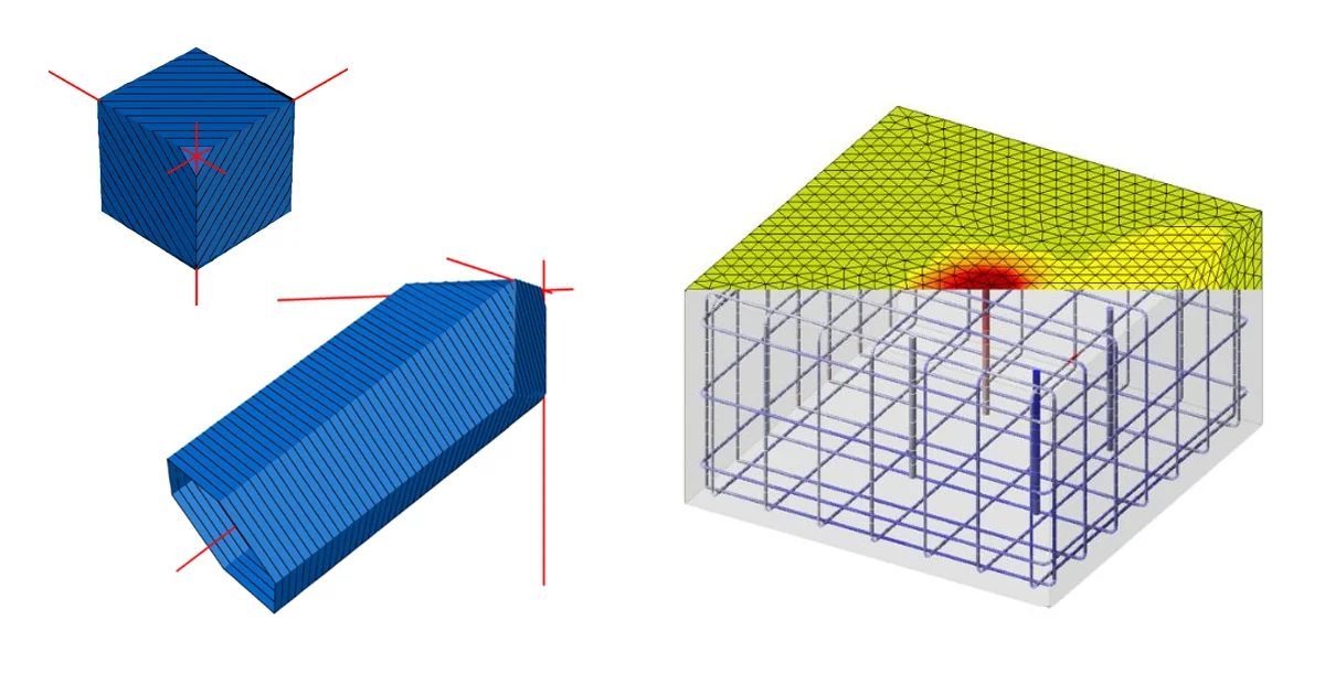
Detail 3D is essentially an extension of the current established IDEA StatiCa Detail application. It adds a new Model type 3D and with this comes the implementation of a method for calculating stress fields in 3D space called 3D CSFM. Calculations and checks are implemented for the Ultimate Limit State.
Before going into the description of the functionalities of Detail 3D it will be good to point out the existence of Theoretical background, where you can read more technical details about the individual model entities and the calculations themselves.
In the first step, the user can select a new Model type on the initial screen (in the wizard), where several templates are available, and of course, the option to enter a model from scratch.
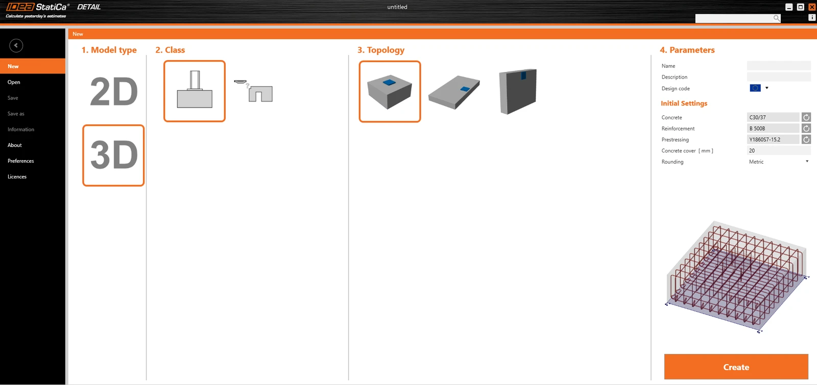
As for 2D models, you can edit the Initial settings in the right part, such as Design code, Materials, and Concrete cover.
After creating a blank model or a model from a template, options familiar to the 2D modeling environment are available.
Options for working with multiple Project items can be found in the top ribbon, as well as the now standard Undo/Redo buttons, Labels view options, Gallery controls, calculation settings, and template management controls.
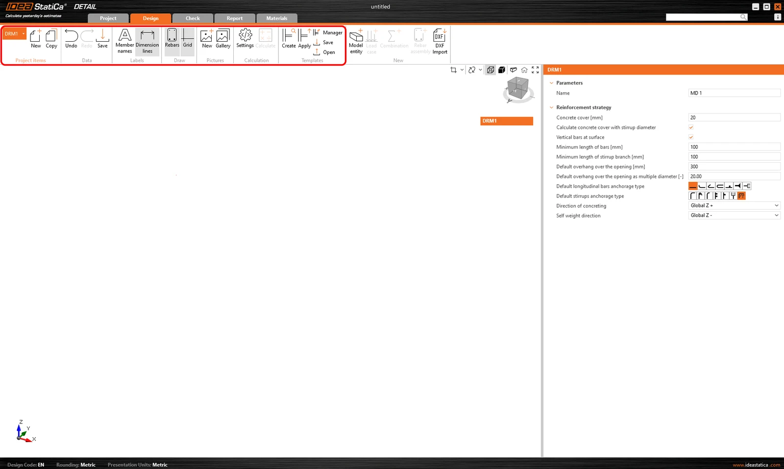
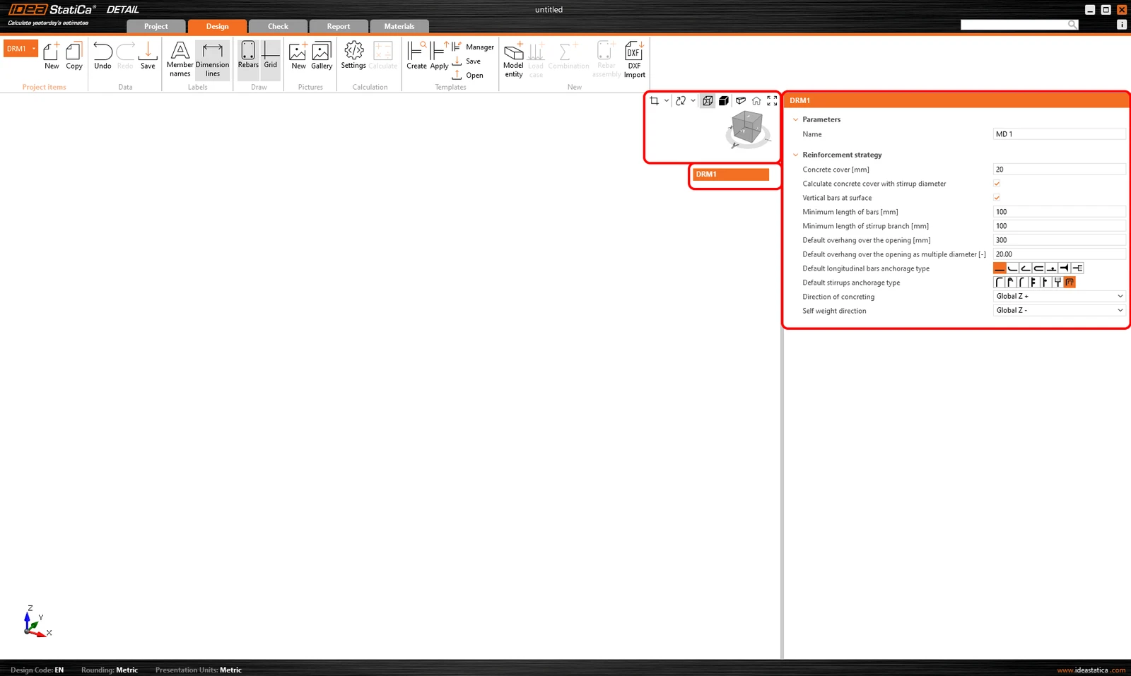
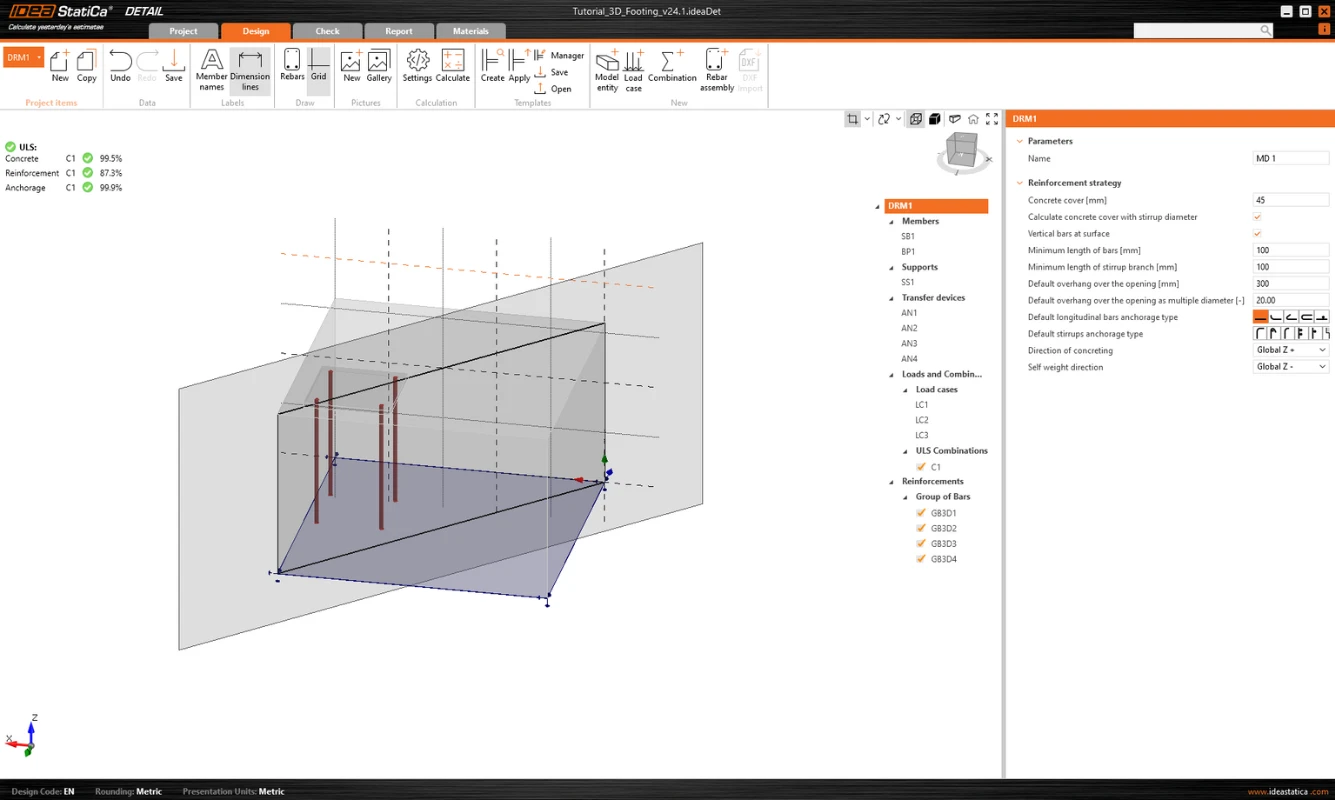
It also initializes the tree, whose first item, called by default DRM1, contains the default settings for the actual Project Item. Above the tree, you can find tools for manipulating the model.
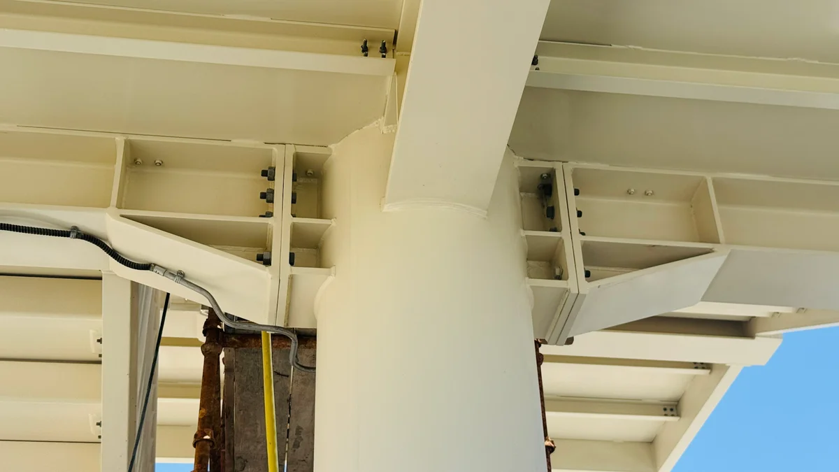
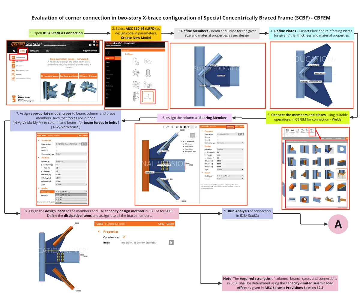
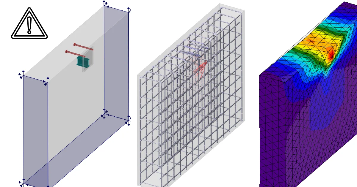
SCBF - Corner Connection Part 1
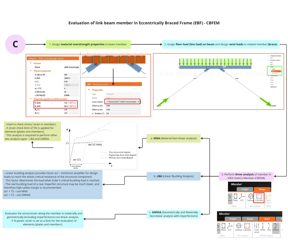
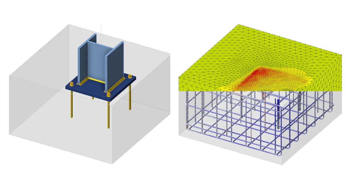
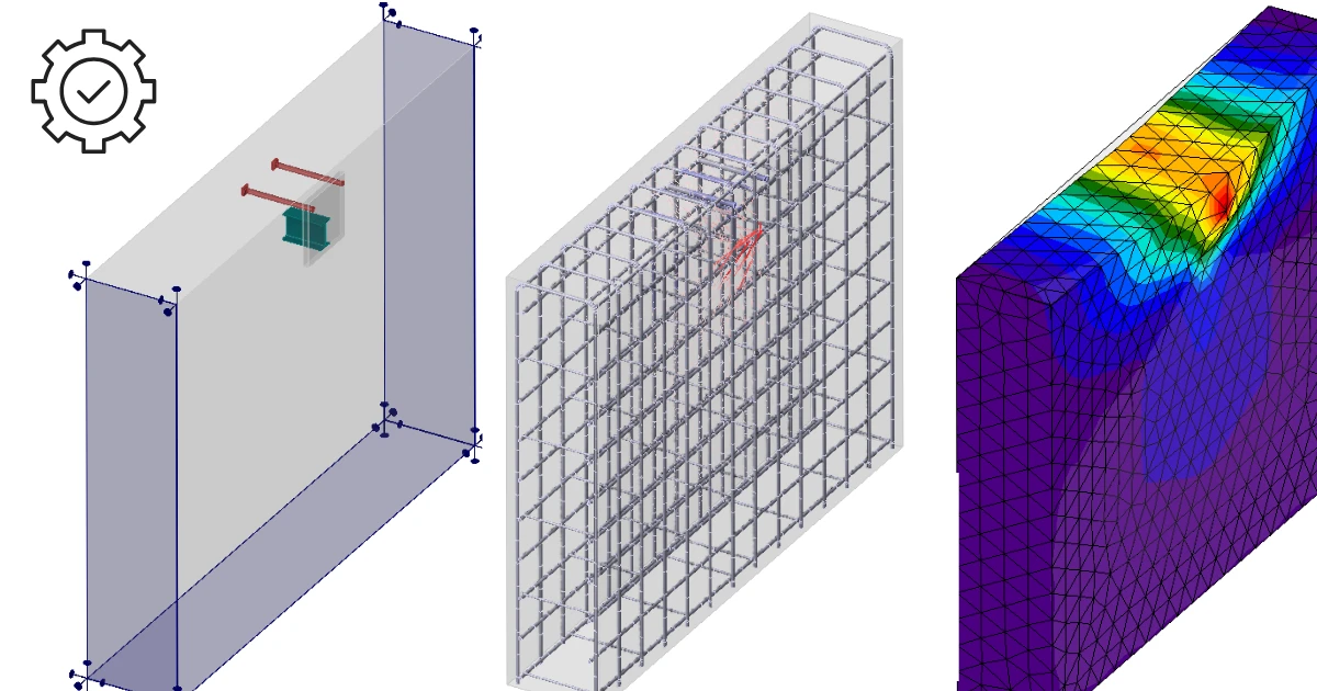
EBF - Part 5
Modelling
Model Entities
We include the following in the Model entity category in the Detail application:
- Members
- Supports
- Load transfer devices
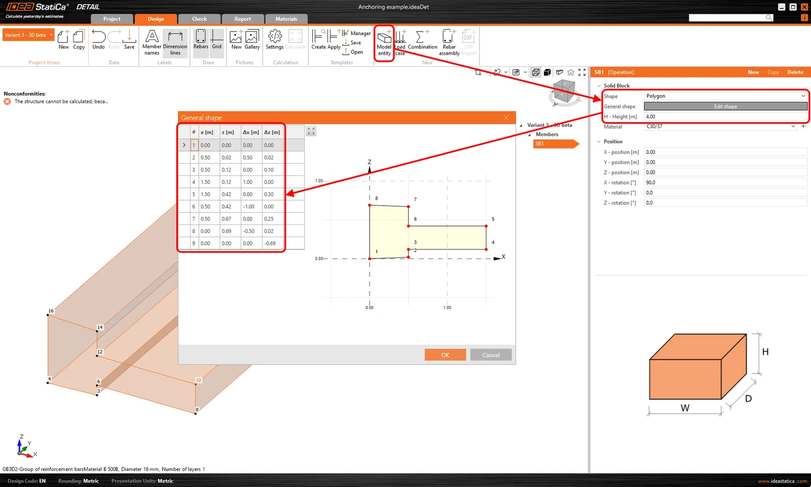
Only one Member can be input, which can be defined as a Rectangle or Polygon shape. A rectangular shape is defined by three dimensions, while for the Polygon option, the shape in 2D space is entered into a table using coordinates, which can then be extracted into space. To define the general shape of a polygon, individual coordinates can be filled in the table, or a copy-paste from a spreadsheet program (such as Microsoft Excel) can be used.
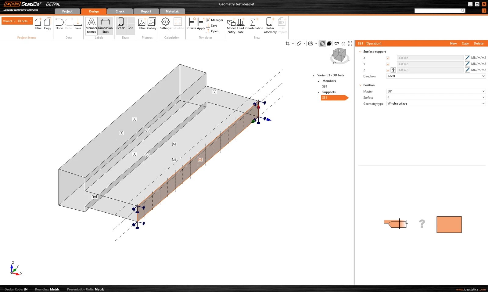
Surface support is used to support the model. This type of support can be specified in two ways - two Geometry types.
- Whole surface
- Polyline
In both cases, you need to choose a reference surface and of course, define degrees of freedom. The support can be defined as elastic and the Compression-only type can be used for a direction perpendicular to the specified surface. In the following figure, we can see the support input on the Whole surface number 4 and the Compression-only option turned off.
For the second option of polyline input, the same table is available as for Members input. Again, you can use the copy-paste functionality or enter the coordinates manually. The entered shape can be moved along the reference surface using X and Y coordinates or rotated by entering an angle.
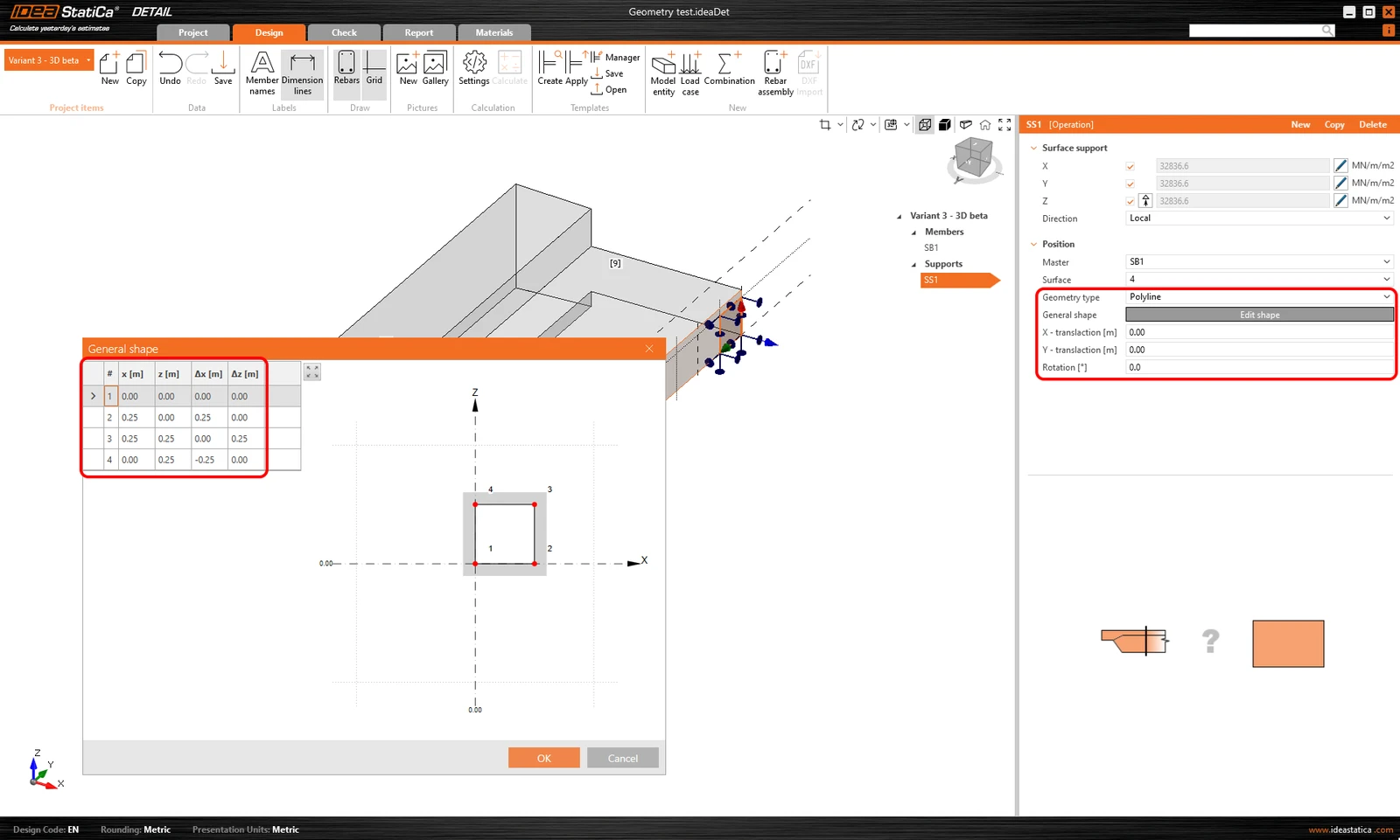
Note that it is possible to specify a polyline so that the origin of the coordinates is at the center of gravity of the desired shape. The position will then be referenced by the X and Y coordinates to that center of gravity.
Stiffness of supports for foundations
During modeling, we can consider two cases. If we model anchorage to structure, the supports can be assumed to be infinitely stiff.
In the case of anchorage into a foundation block, the stiffness must be defined correctly. In addition, the supports must be defined as compression-only.
The values in the z-direction (stiffness Kz) are taken from the literature according to the appropriate soil type. A specific example can be found in the tutorial.
The values depend on the recommendations of the relevant regional literature. Alternatively, the values are obtained from the geotechnical engineer.
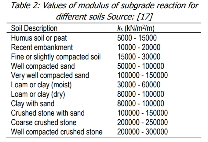
In the horizontal directions (Kx and Ky), the situation is less straightforward. Our general recommendation is to use a value of approximately 1/10 of Kz together with engineering judgment.
A more accurate approach would be to use an iterative procedure, from which we derived our recommendation.
First, set Kx and Ky to very low values (for computational reasons, it is not advisable to set the value directly to zero), but for example 0.1, and examine the reinforcement stresses.
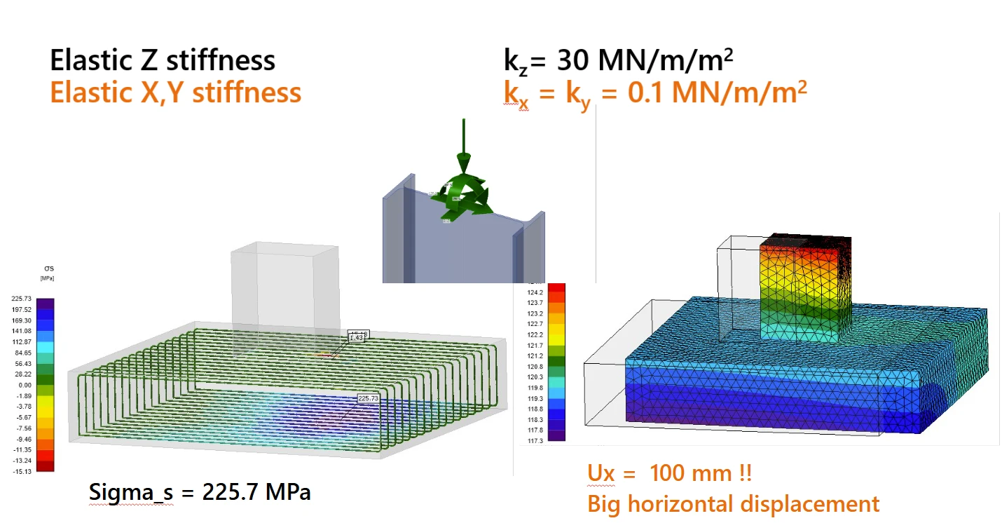
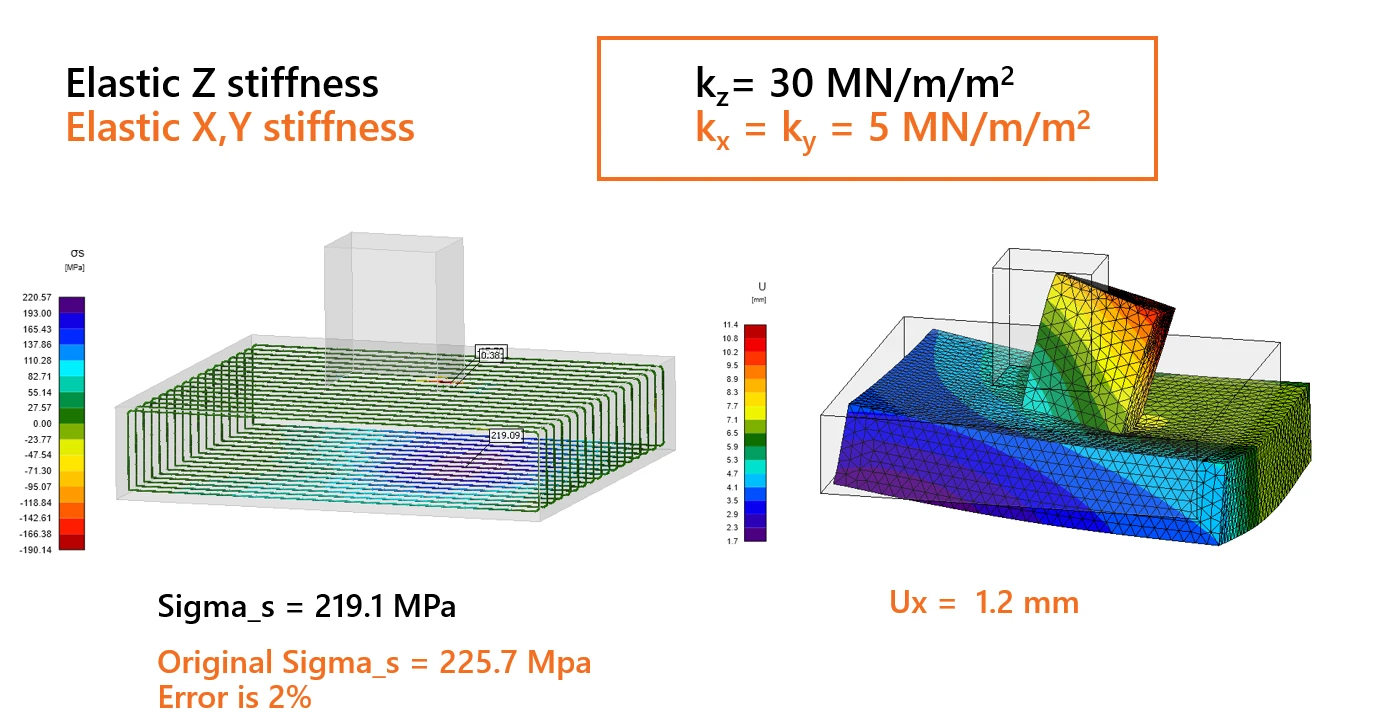
Since these low values result in unrealistic displacements, the stiffness should be gradually increased to better reflect reality. The goal is to achieve more realistic displacement values while keeping the reinforcement tensile stress at the bottom edge close to the original value, with a deviation of less than 5%.
Load transferring devices
Load transferring devices contain two entities the base plate and single anchor. Let's start with the Base plate. To specify the position, a reference surface and edge must be selected. These define the origin of the coordinates from which the X and Y distances are measured. There are two shape definition options, Rectangular and Polygon.
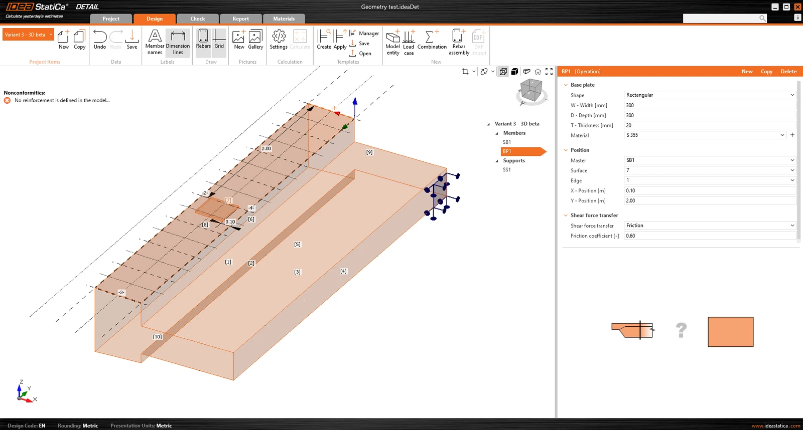
The base plate is connected to the concrete element by a contact that transfers compressive stresses and, if the user chooses, can also transmit shear stresses. There are three shear transfer mechanisms that can be selected:
- by friction
- by anchors
- by shear lug
The software does not allow you to combine these shear transfer mechanisms.
For the option by friction, the design value of the friction coefficient needs to be entered. For the option by shear lug, the steel profile, including geometry and position, needs to be inputted.
All the possible configuration of base plates can be found in the article: Base Plates Options.
The base plate can transmit either a point load or a group of forces. For a point load, the model can be loaded with six internal forces (Fx, Fy, Fz, Mx, My, and Mz) at any position on the base plate. For a group of forces, users can input the forces’ positions, intensities, and directions into a table, allowing for a general positioning on the base plate. It is important to mention that the base plate is point-loaded and doesn't have any stiffener or member welded on its upper face. Thus, for correct load distribution, it is important to use a relatively stiff base plate with relatively high thickness. Another option is to use Stub, that handless the issue with the plate stiffness.
A second load transfer device, the single anchor, can be added and interconnected with the base plate to create, for example, a base plate of the column anchored with four anchors (see the figure below). It is also possible to model separate anchors without a base plate.
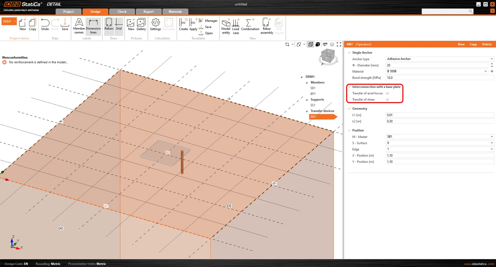
More information about the interconnection with the base plate can be found in the Theoretical background.
In terms of position and geometry, the anchors are referenced to the surface and edge of the block, including the determination of the relative position as with the base plate. Of course, it is possible to specify the length of the anchor in the concrete and the length above the concrete surface.
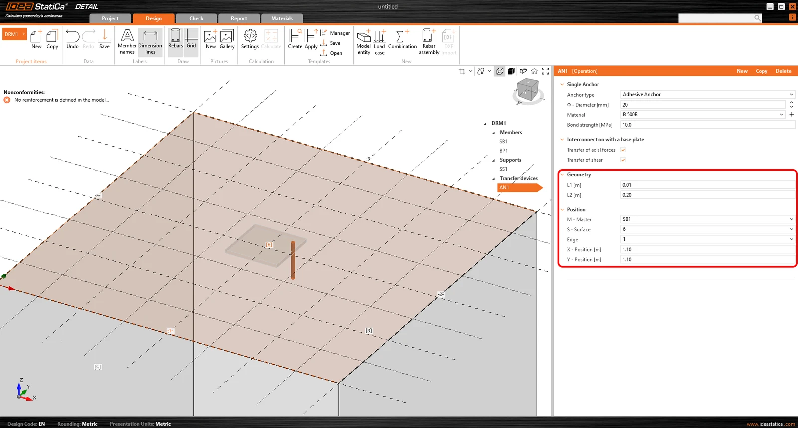
The anchors are implemented in two variants:
- Cast-in-place
- Adhesive anchors
For the Cast-in-place Reinforcement, the Bond strength is used according to EN 1992-1-1 chap. 8.4.2. In addition, it is possible to specify the Anchorage type for this type of anchor as for conventional reinforcement.
For Adhesive anchors, it is possible to directly input the bond strength, which the user can find out from the technical data sheet of the applied adhesive mortar. Note that it is necessary to input the design value of the bond strength. The following article will help you find the value.

See all anchors options in the article: Single Anchor Options
A thorough description of the behavior of the interconnection between the anchor and base plate is described in the Theoretical background.
Loading and combinations
Loading
Load cases can be defined in the same way as for 2D reinforced concrete elements. This means that each load case can be assigned either a Permanent or a Variable load type. The Permanent load cases are applied to the model first, and after a successful calculation, the Variable load cases are applied.
Type of load impulses
A total of 4 types of load pulses can be added to each load case.
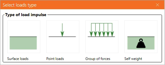
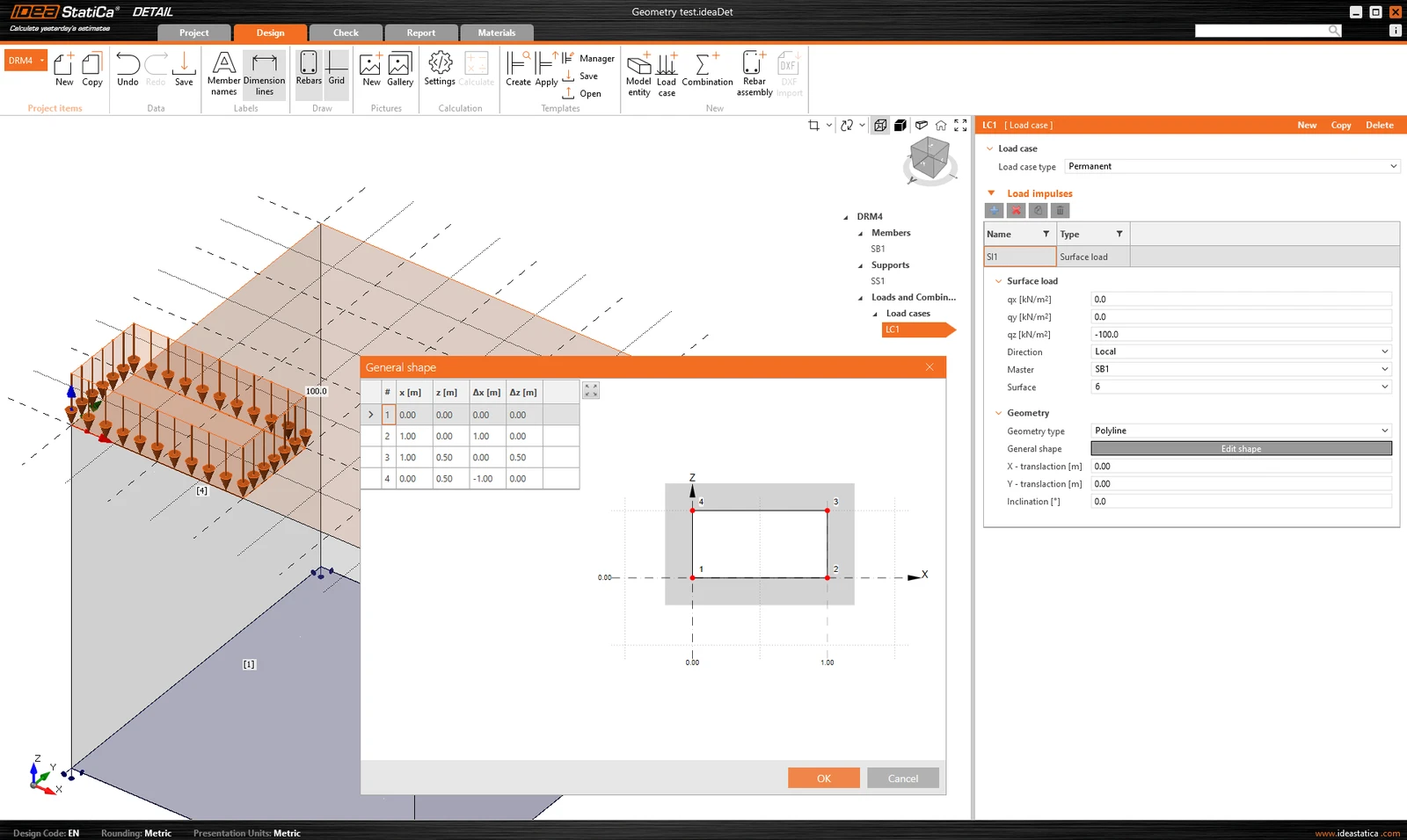
The definition of Surface loads is identical to the definition of Surface support. This means it is possible to specify it in two ways: Whole surface and Polyline. In the case of Surface loads, of course, the load intensity is entered in the three general directions.
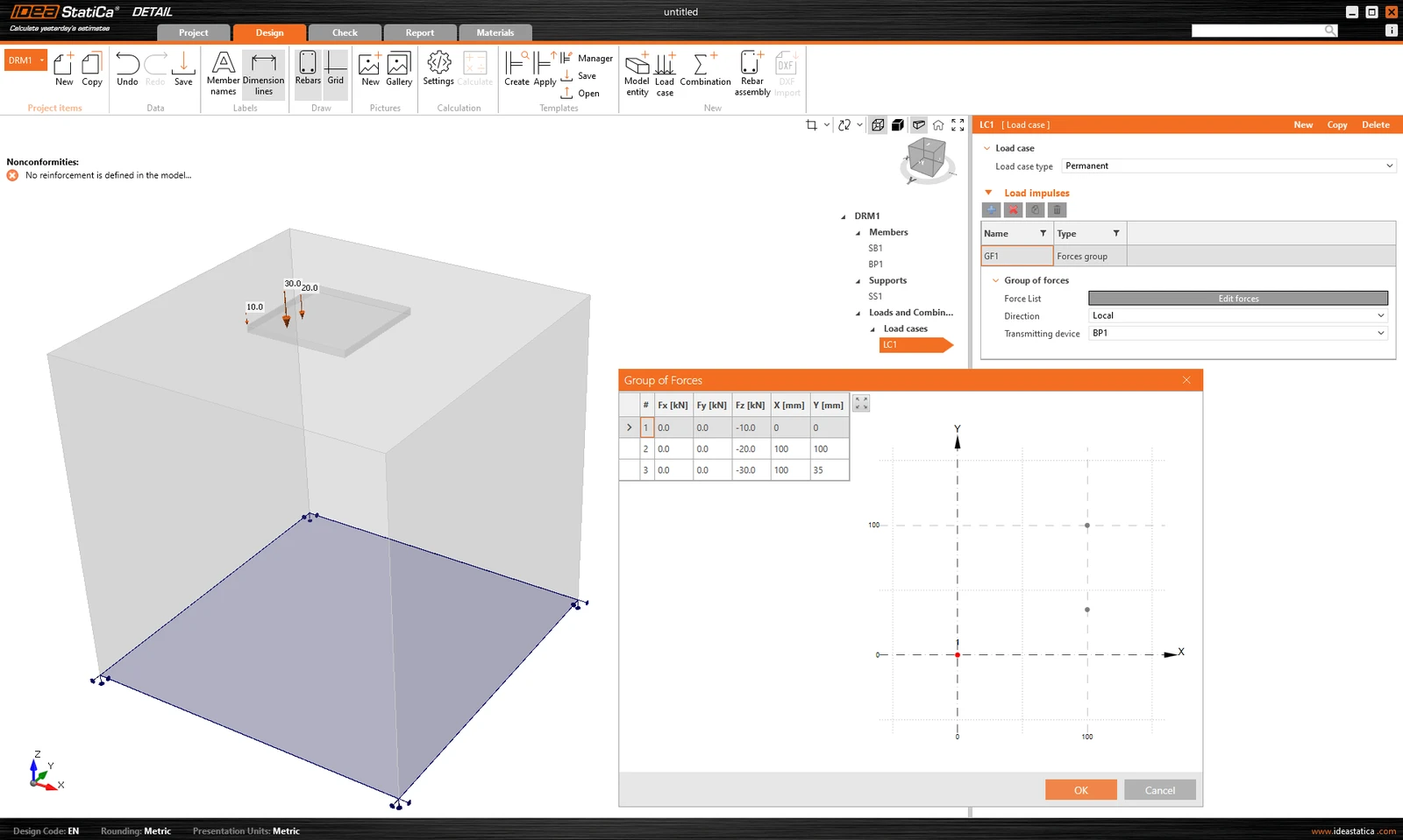
Group of forces is a load entity that allows you to specify forces in three directions anywhere on the model using a table. It can be referenced to the base plate or the surface of a concrete block. For tabular input, it is again possible to use the copy-paste functionality from the spreadsheet program.
The self-weight should be included in every model. For example, concrete foundations loaded with a bending moment will not so easily overturn.
Point loads can be loaded directly to the base plate with six internal forces Fx, Fy, Fz, Mx, My, and Mz in the general position.
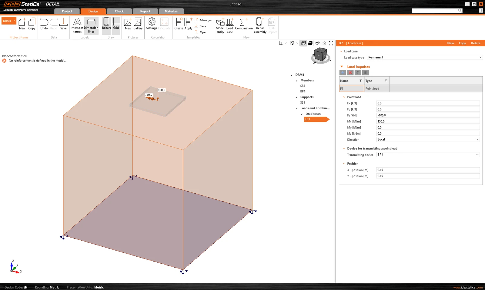
When using a base plate, applying this force directly to a realistic, deformable base plate can lead to unrealistic stress redistribution across the plate, anchors, and concrete. It is therefore more appropriate to use the second option - the stub.
The Stub
The stub is represented by a short part of the column above the base plate, which is modeled as a shell element structure and behaves as a physically accurate interface between the internal forces and the plate. A standard section database is used.
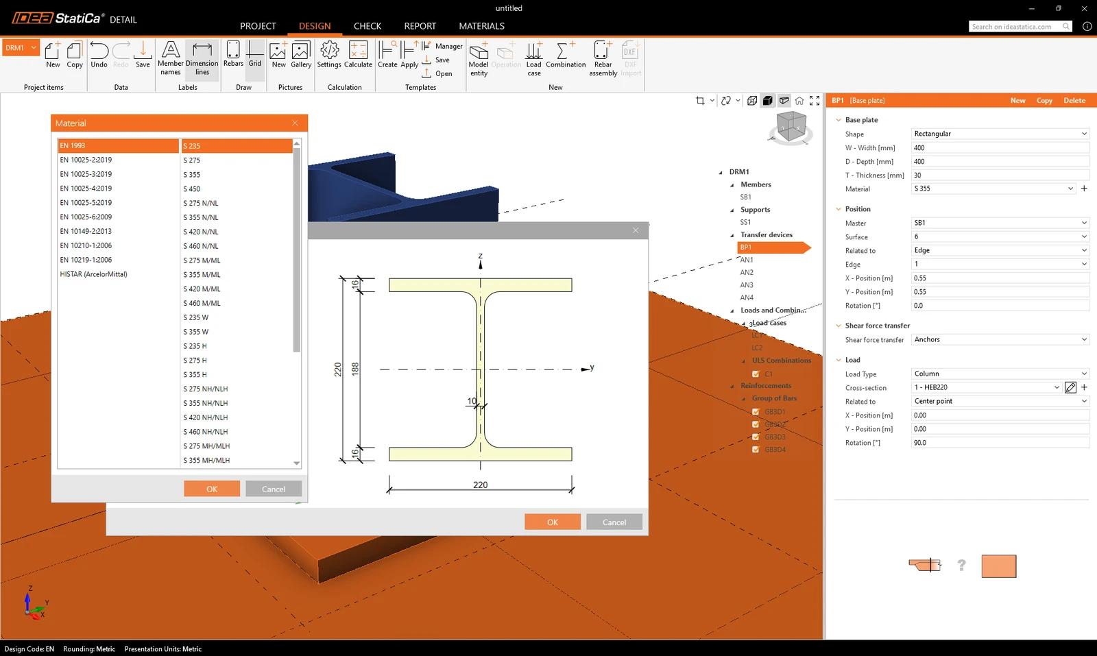
The 6-component internal force set (forces and moments) is applied at a single point on the bottom face of the stub - i.e. the base of the column.
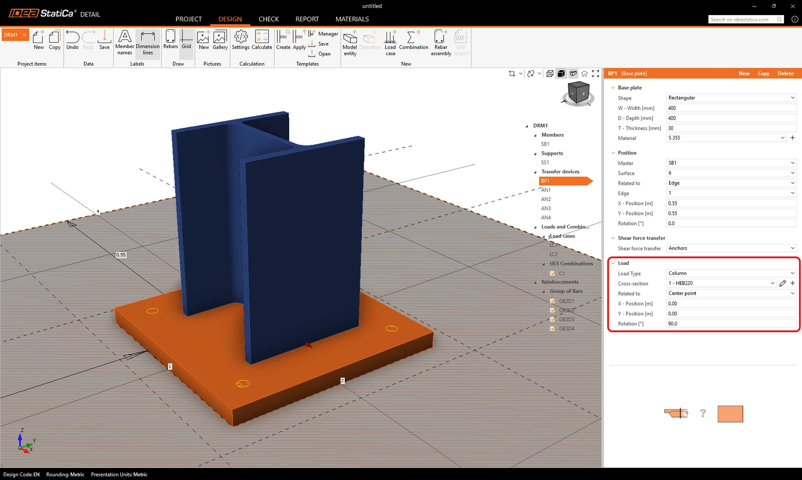
Constraints transfer the forces to the top face of the stub, from where they are naturally redistributed through the stub into the base plate, anchors, and concrete.
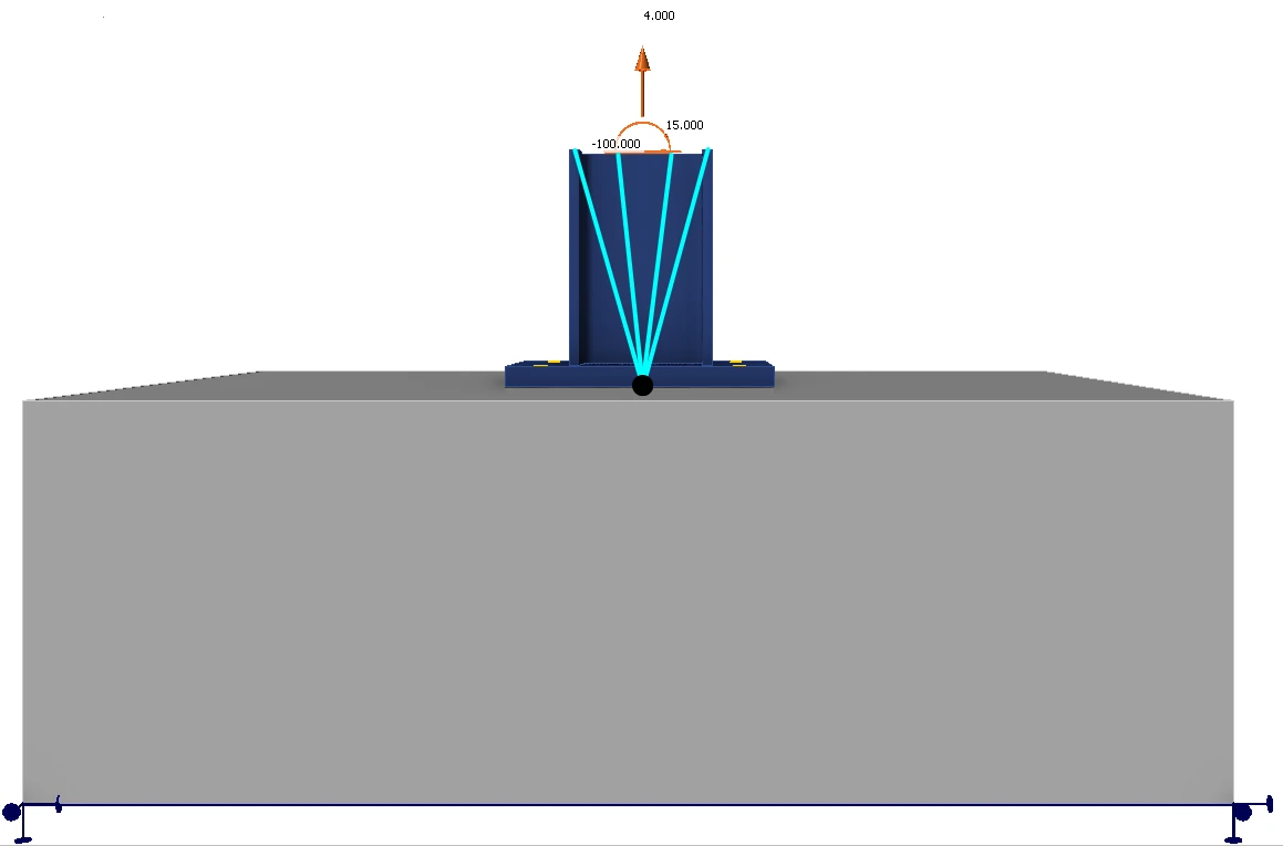
This approach preserves the realistic stiffness interaction between column and plate and eliminates the need for any manual redistribution or artificial assumptions.
The stub was released in IDEA StatiCa version 25.1.
Combinations
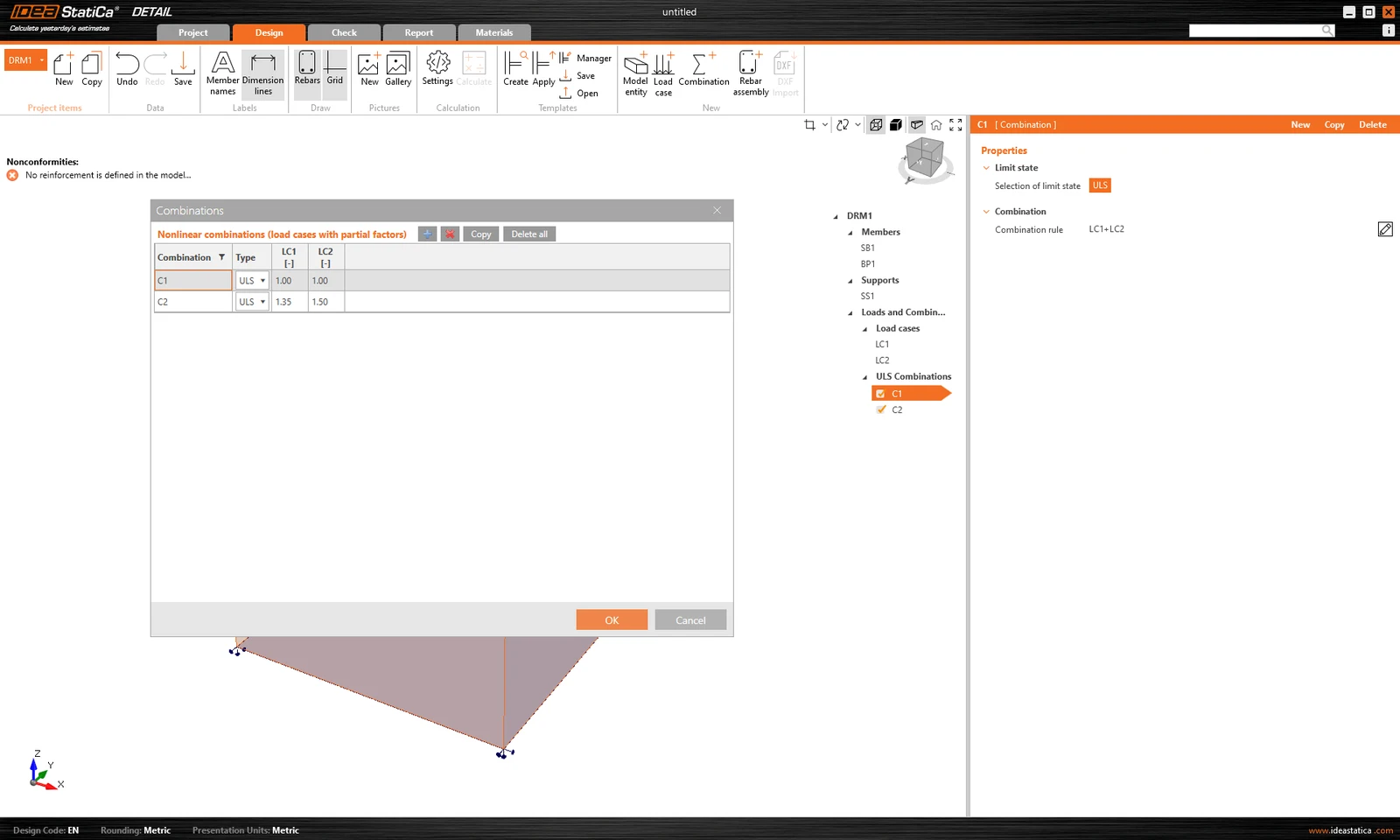
Because the analysis in IDEA StatiCa Detail is non-linear, so-called non-linear combinations are used. This means that individual load cases are not calculated and the results are not then added together. On the contrary, load cases of the same load type are added together before the calculation, of course with the respective coefficients defined in the combinations, and the individual combinations are then calculated. This is why the existence of at least one combination is a prerequisite for starting the calculation.
Only combinations for ULS can be defined.
Try out the new features of IDEA StatiCa today
Download the latest version for freeReinforcement
In the following article, we will first explain the basic principles of modeling, and later show advanced options suitable for complex examples and atypical shapes.
- Basic Principles
- Advanced Options
Basic Principles
Four Reinforcement Entities
Reinforcement is created through the Rebar assembly command, which offers four separate entities:
- On more edges — places reinforcement along a list of edges or surfaces
- On surface — positions rebars relative to a single reference surface and edge
- By two points — defines a bar directly between two coordinates
- On polyline — defines a bar shape from a list of points
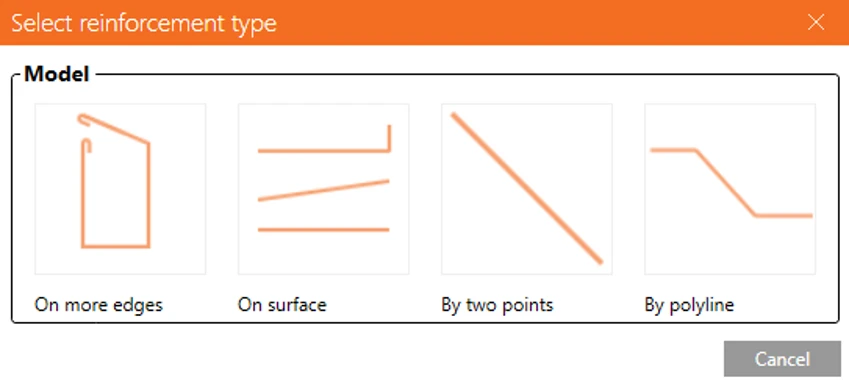
The basic principle of placing reinforcement for both the On more edges and On surface options is that you first need to select a master (reference) element, and then choose the appropriate reference surfaces and edges based on the master element's numbering — see example.
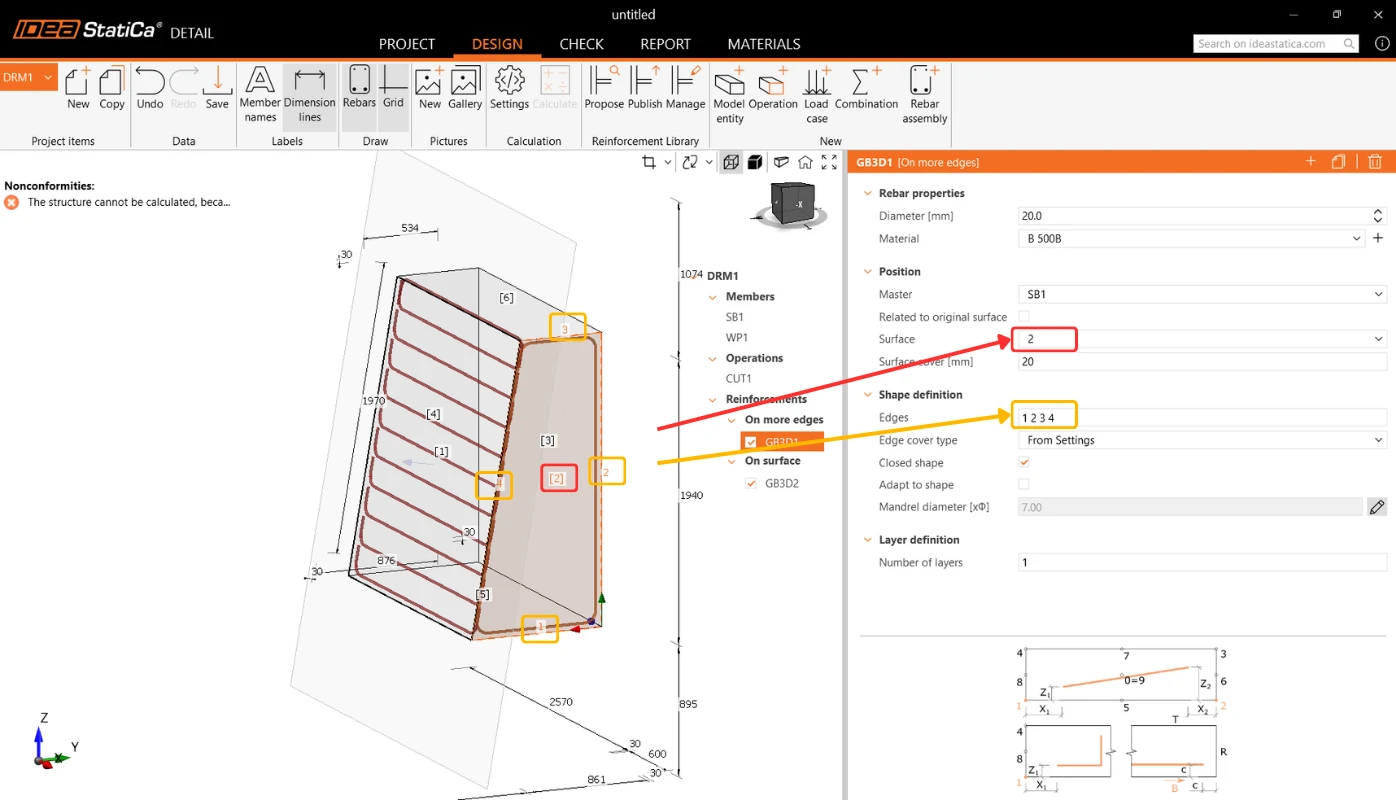
Beyond that, each type has some shared property settings available, such as bar spacing, anchorage type, and others, as well as some settings unique to that specific definition — for example, the On more edges entity can be set as closed, and so on.
The other two reinforcement entities, by contrast, are defined using coordinates or vectors.
By two points can be defined in multiple layers, replicated along a vector, referenced to master element — or in global coordinates when no relation to a model entity is wanted.
A polyline is defined using a table for entering points, including the ability to paste values directly from Excel via copy-paste. The polyline can be defined relative to a model entity — to the origin of an edge (the local coordinate system cross is drawn) or to the centre of a face — or in global coordinates.
Advanced Options
Reinforcement Reference Geometry
In addition to a solid block, the Master for a reinforcement entity can also be assigned as a negative volume or a working plane.
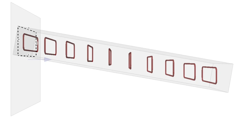
- Working plane — a general section through the body, defined either by a normal vector or by three rotation angles. Basic reinforcement shapes are defined in the plane, which is far easier than working directly with complex 3D geometry.
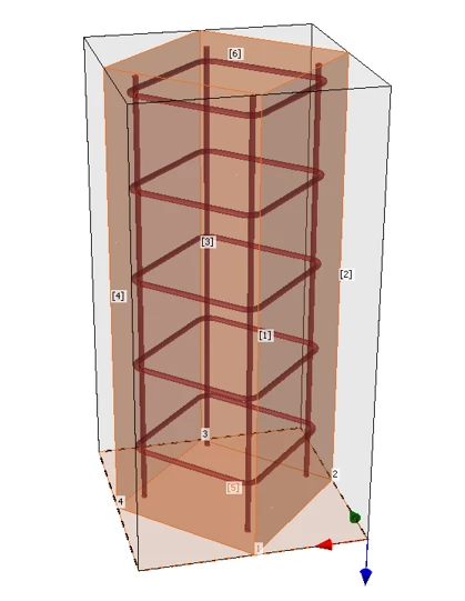
- Negative volume — can be placed anywhere in the body, can be even rotated, with reinforcement built directly into it.
Closed Shape for Stirrups
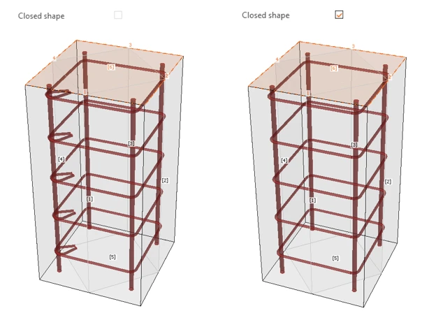
The Closed shape property connects the first and last points of the reinforcement shape into a continuous bar. Anchorage type settings are disabled, and the scene shows a closed stirrup without hooks. Because the stirrup is modeled continuously instead of being terminated by anchorage springs, the artificial discontinuity is gone – and so are the result peaks it caused.
Reinforcement Adapts to the Shape of the Block
The Adapt to shape option controls this behavior: when active, the individual bars in a layer adjust to follow the shape of the referenced solid or negative volume; when inactive, all bars keep the shape defined on the input surface. Both behaviors are supported as legitimate design intents, and the applicable mode is selected explicitly rather than fixed by the tool.
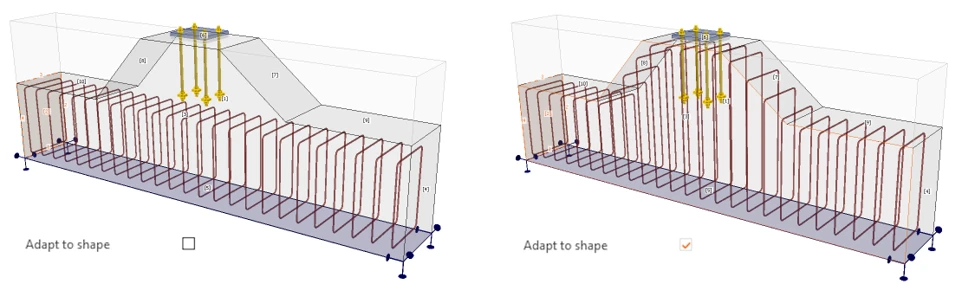
Regular and Irregular Spacing
Layer spacing has two options for Spacing definition:
- Regular takes a single distance value
- Irregular accepts a list of distances — so a non-uniform layout is entered directly instead of being split into several entities.
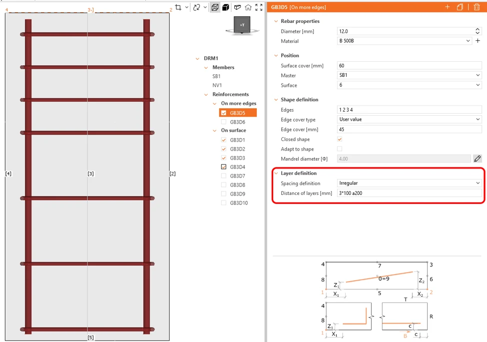
Reinforcement that extends beyond the block is trimmed automatically, regardless of which Master type was used.
Note: Advanced reinforcement design options were released in IDEA StatiCa version 26.1.
Import of anchoring from Connection to Detail
Anchoring in a plain concrete block can be modeled and code-checked in IDEA StatiCa Connection. For certain cases, such as anchorage near the edge, the design is insufficient due to possible failure modes, and additional reinforcement is required. Although, this capability isn't available within the Connection app, it is possible to continue directly into the Detail application.
3D Detail is focused on solving anchoring into concrete blocks and analysis of both the anchoring elements and the concrete block itself. Moreover, a direct link is implemented between the Connection and Detail applications to simplify the process. Connection users who design anchoring according to Eurocode or AISC can import their model from Connection to the advanced 3D Detail by one button click.
- Import is allowed just for anchoring. If there is no concrete block in the Connection model, the export to Detail is disabled ("RC check").
- The model in Connection has to be calculated. If results are not available, the export icon ("RC check") is disabled. For export functionality, it is also necessary to have valid licenses for concrete applications. Otherwise, the export option will be disabled again.
- Only one concrete block for the import/export is allowed.
- Some anchor types are not supported for import, and we also do not recommend exporting so-called edge anchoring. A detailed breakdown of the limitations is provided in the article: Known Limitations for 3D Detail
The connection is imported, including
- The concrete block
- Anchors
- The base plates
- Loads
Additional information and parameters that are set according to the corresponding settings in the Connection:
- Shear transfer (through Anchors, Shear lugs, and Friction)
- Material
- Anchorage Type
- Anchorage type at the end
- Friction coefficient
The possible configurations and types of anchors that can be exported can be found in the following articles:
Export from Connection to Detail step by step
First, create a model of anchoring in Connection according to Eurocode/AISC and click the Calculate button.
When results exist, export of footing is enabled. By clicking the button "RC Check" in the ribbon, a dialog asking for the location and the name of the newly created Detail file appears.
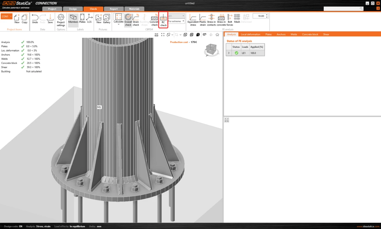
After a successful export, the project in Detail is created. The geometry of the concrete block and the base plate, the position and properties of anchors, and the load are automatically transferred to Detail. Surface support placed at the bottom surface of the concrete block is automatically created.
Note: It is only necessary to check the settings in the Z direction. (For foundation footings, we use compression-only with the soil stiffness setting; for a continuing structure, we can also enable tension support).
The most tricky part of this process is the import of the load. For every calculated load effect in Connection, the corresponding load case and the ULS combination are automatically created in Detail.
- The base plate is loaded by forces in welds, which are modeled as a Group of forces. For the loading of the base plate itself, the imported loading is represented by a group of forces following the stresses in welds between the base plate and steel members in the Connection model.
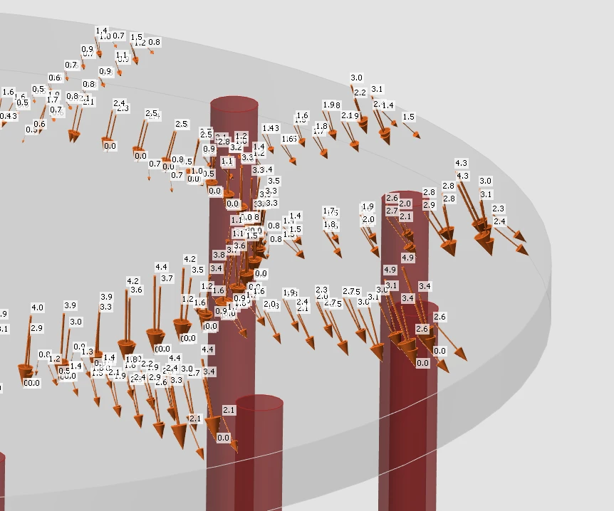
- Anchors are modeled and loaded independently from the base plate, and they are axially loaded by point loads. The loading of anchors is represented in the scene by a double of arrows in opposite directions. One arrow represents the tension force acting only on the top of the anchor. The other one represents the compression force acting on the base plate.
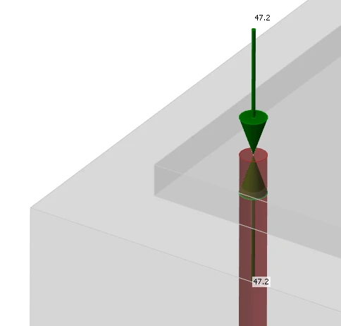
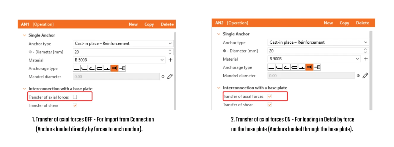
The Checkbox "Transfer of axial forces" is unticked by default as the anchors are loaded by forces directly.
Note: The following figure does not apply to cast-in plates, where axial force transfer is correctly checked after export. The reason for this can be found in the Theoretical Background.
- Shear is transferred according to the setting in Connection by one of the options – anchors, shear lugs, or friction. If the shear force is transferred by anchors, you can turn off specific anchors by unticking the checkbox "Transfer of shear".
- If friction or shear lugs are set, shear in the anchors is never considered in the model. (Even if the checkbox is selected.)
Then just add the required reinforcement using the tools mentioned above and calculate the model. Don't forget set the Design Bond strength for adhesive(post-installed) anchors according to the manufacturer’s parameters.
It is also a good idea to check that the specified load will not overturn the concrete block. Overturning can be prevented by self-weight or sufficient compressive normal force. If the resultant vertical force is positive (the block will be lifted off the support), the calculation will also fail.
Since the concrete does not act in tension, the cover between the bottom reinforcement and the support will be peeled off.
A thorough explanation of imported forces acting on the base plate or anchors, which are shown in the figure below can be found in the Theoretical background.
One-way sync from Connection to Detail
The Connection application provides an “Update Existing” function to synchronize a Detail project with the latest Connection data, eliminating the need to recreate the model from scratch.
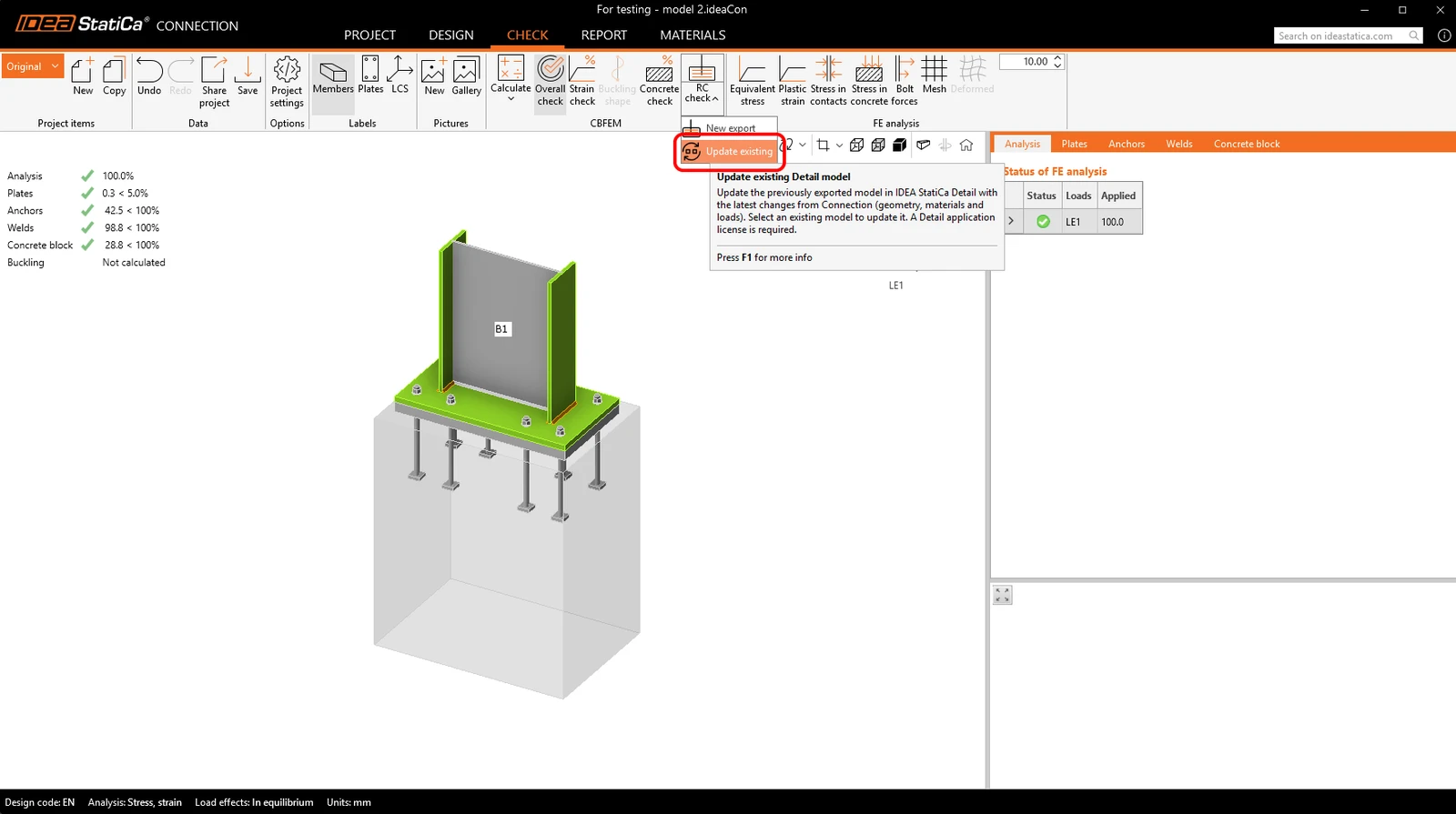
The update process synchronizes the following data:
- Concrete block: geometry and material
- Base plate / cast-in plate: geometry and material
- Anchors / fasteners: geometry and material
- Load data: load cases, impulses, and combinations
The settings are not imported/synchronized, so code must always be set correctly.
During the update, entities originally created from Connection are handled as follows: existing entities are updated with the new data, entities no longer present in Connection are deleted, and new entities in Connection are added to the Detail project. Entities created directly in Detail remain unchanged, including negative volumes, cuts, boolean operations, reinforcement, plates, anchors, and load cases.
Before updating, the system asks to create a backup, and backups are automatically stored in the same folder to ensure recovery of the previous state.
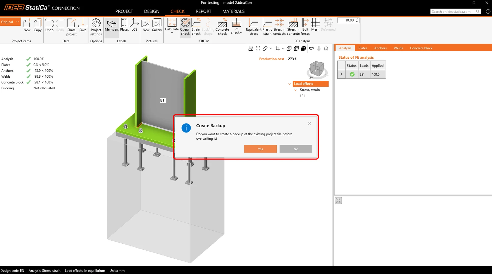
The workflow supports multiple project items in both Connection and Detail. It is possible to copy a Connection project item to create a variant and then synchronize it with the corresponding Detail project. Updates are also supported for Detail projects containing multiple project items, allowing all relevant data to remain consistent.
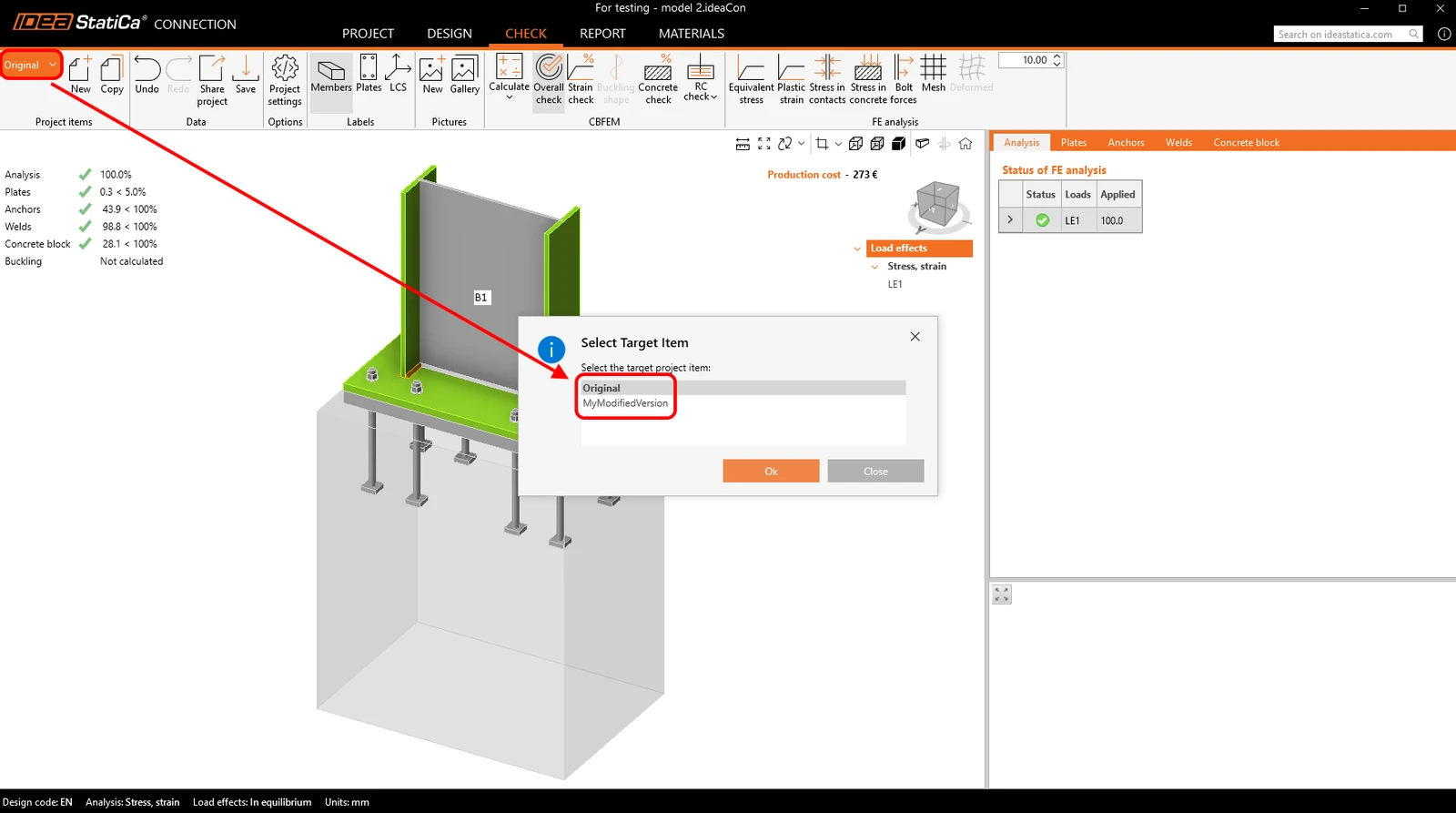
Note: Released in IDEA StatiCa version 24.1. for EN. Gradually improved by implementing AISC, adding anchoring-element options, and refining the limitations. This article, including the full functionality, is applicable as of version 26.0. The individual changes can be seen in the release notes.
Try out the new features of IDEA StatiCa today
Download the latest version for freeResults
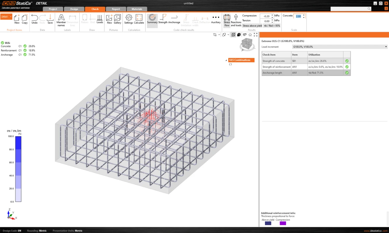
The display of the results is very similar to 2D Detail. However, there are some major differences, especially when it comes to results on concrete and results of anchors. In the following section, we will go through all the available results, focusing on the differences mentioned. In the check tab you can view a total of 4 types of results:
- Summary
- Strength and Anchor check based on codes
- Anchorage of the reinforcement and Anchors
- Other additional results
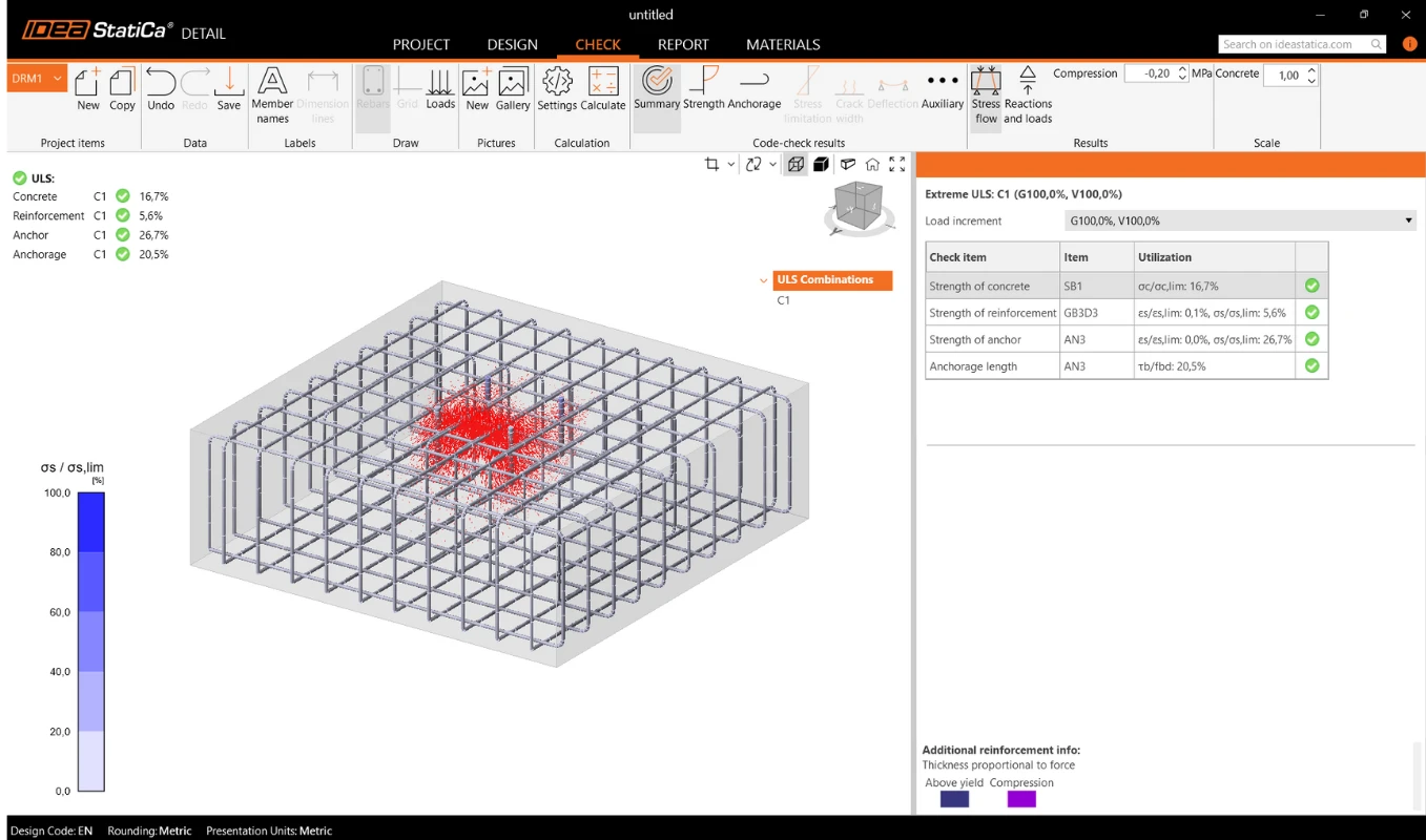
Stress flow in Summary results shows you the vectors of compression principal stresses in concrete and utilization of the reinforcement and anchors to give you a basic overview.
Strength check of concrete, reinforcement and anchors
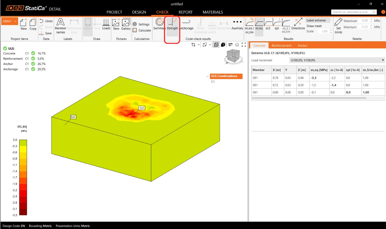
In the Strength check, you can display the distribution of stresses and strains for concrete. In the top ribbon in the Results toolbar, you can control what will be displayed. It is also possible to display the ratios σc,eq/σlim, and ε/εlim as well as the plastic strain, the level of triaxiality σc3/σlim, and the direction of principal stress for concrete. All results in the Strength are related to the Ultimate Limit State.
Note: Please read the Theoretical background where the σc,eq is defined. Or you can go through this verification article, where this phenomenon is explained and verified using a well-known tri-axial test: Tri-axial stress – the active confinement effect
Materials can be switched in properties.
The check for reinforcement is performed in a very similar way, where we again compare the limit values with the calculated stress/strain - σs/σlim, and εs/εlim.
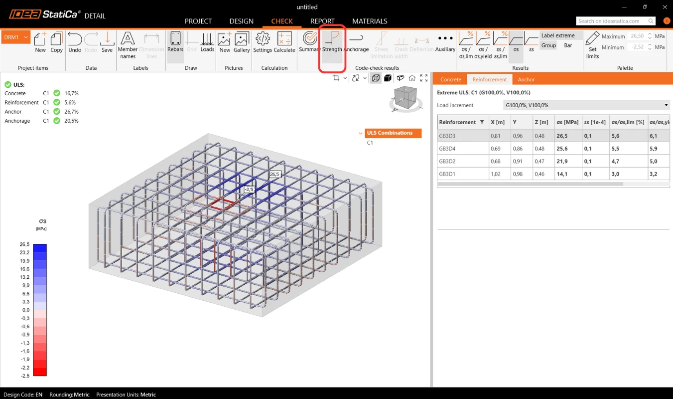
For the anchors, we have two checks. One is the same as for reinforcement — comparing the limit values - σs/σlim, and εs/εlim.
Note: You may notice that each anchor is verified in several positions, which are automatically calculated as extreme cases.
Code-checking of anchors according to the design code
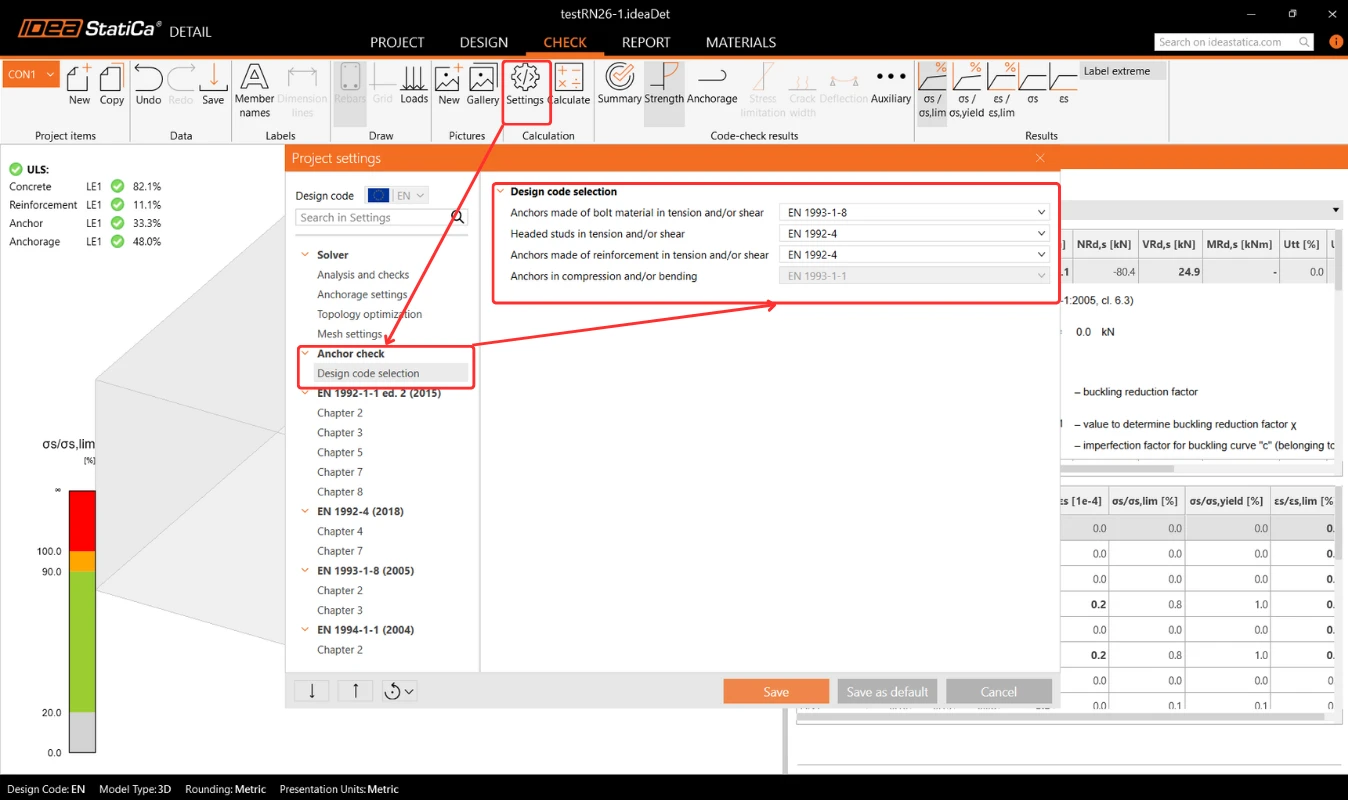
In addition, we have designed code-based checks (EN, ACI/AISC, AUS), which are done according to the standard. The specific standard considered can be seen in the settings, where it is also possible to select a different one depending on the type of anchorage used (base plate in direct contact with concrete, grouted base plate, and base plate with a gap), as well as the required standard based on regional practices.
Implemented codes: EN 1992-4, EN 1993-1-8, EN 1994-1-1, ACI318-19, AISC 360-16, AS3600, AS 5216, AS 4100
The standard settings can be changed in Project Settings, where the chapters will appear according to the standard selected when the project was created. When importing from Connection, It is recommended to check that the same standard is set.
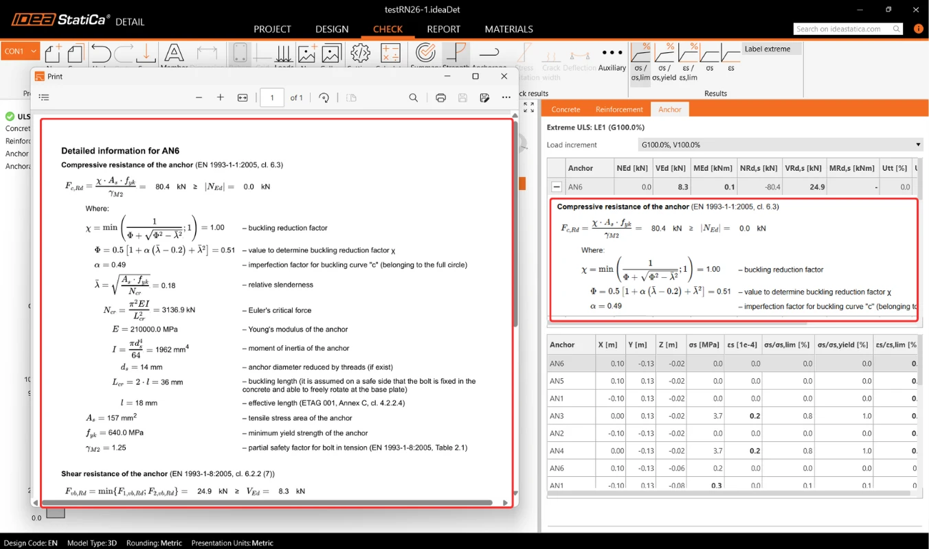
Every row in the anchor check table can be expanded to display the applied governing equation in standard mathematical notation.
The view includes live model values retrieved directly from the active project alongside complete intermediate calculations that link base material properties to final resistance. Each entry contains explicit references to the relevant code section or article, as well as symbol explanations specifying whether values derive from material properties or project settings.
In the Theoretical Background chapter - Ultimate Limit State Checks, each check is explained in detail, including all formulas used.
Note: Finished and released in IDEA StatiCa 26.1.
Anchorage of reinforcement
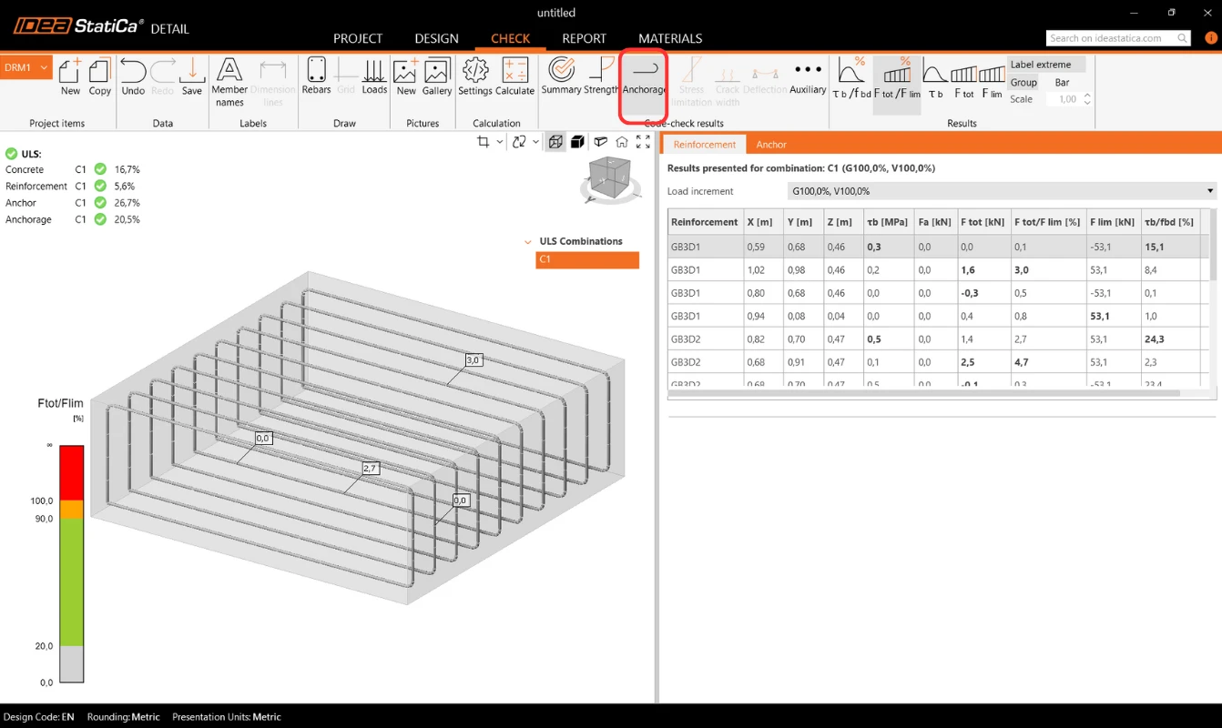
The Anchorage check gives you information about bond stress and total force on the reinforcement and anchors.
Surface support reactions
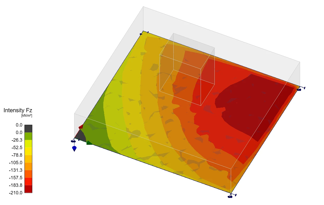
The Reactions and Loads section includes an option to display surface support reactions. Reactions can be viewed in two modes:
- Intensity – Surface reactions are shown on the supported face of the concrete block using isobands to illustrate distribution over the support area.
- Resultant – The resultant reaction for each support is displayed as an arrow at the support’s center of gravity, indicating magnitude and direction.
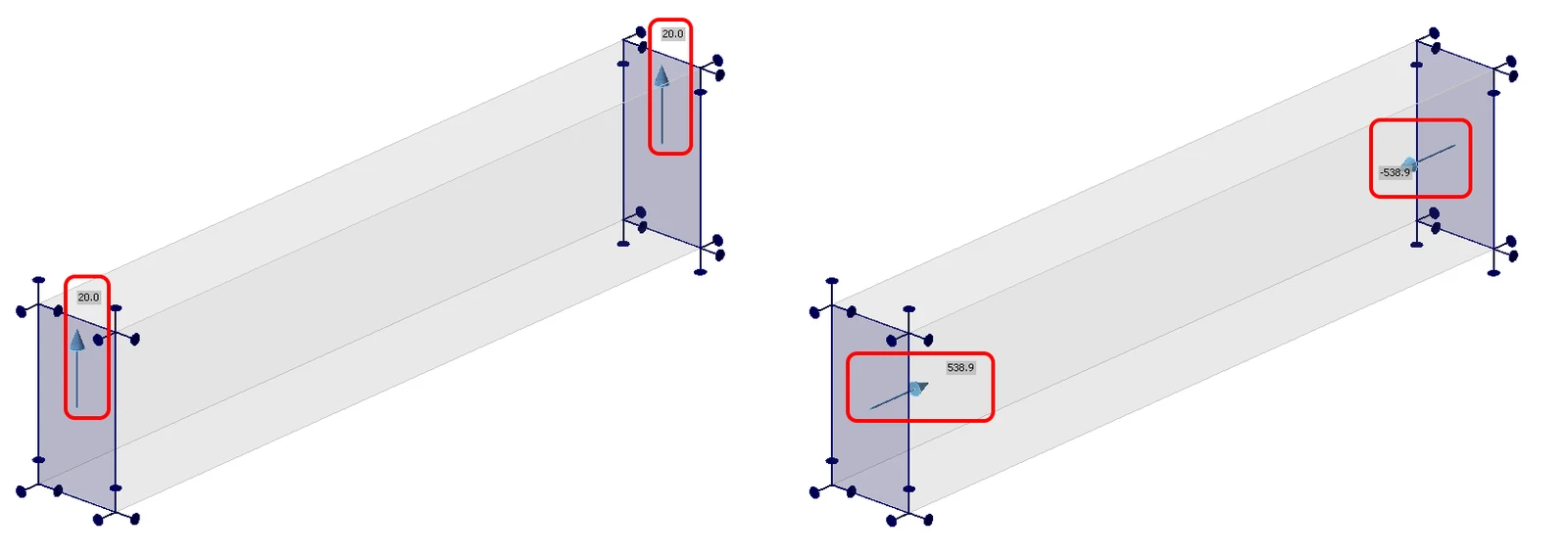
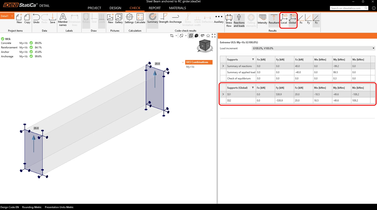
For both modes, reactions can be displayed in either the Global Coordinate System (GCS) or the Local Coordinate System (LCS) of the support.
A new table in the Property Grid lists summarized reactions for individual supports, also available in global or local coordinates.
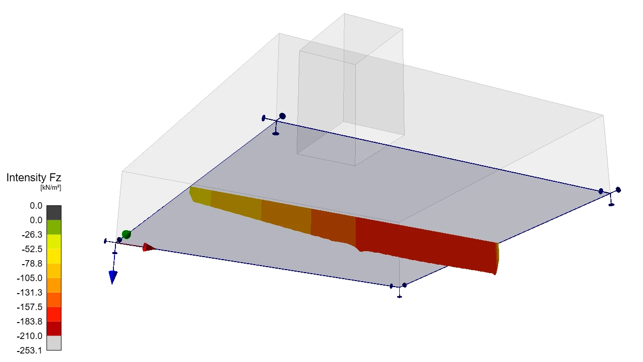
Additionally, reaction distribution can be visualized in section views created by the user.
Additional advanced results
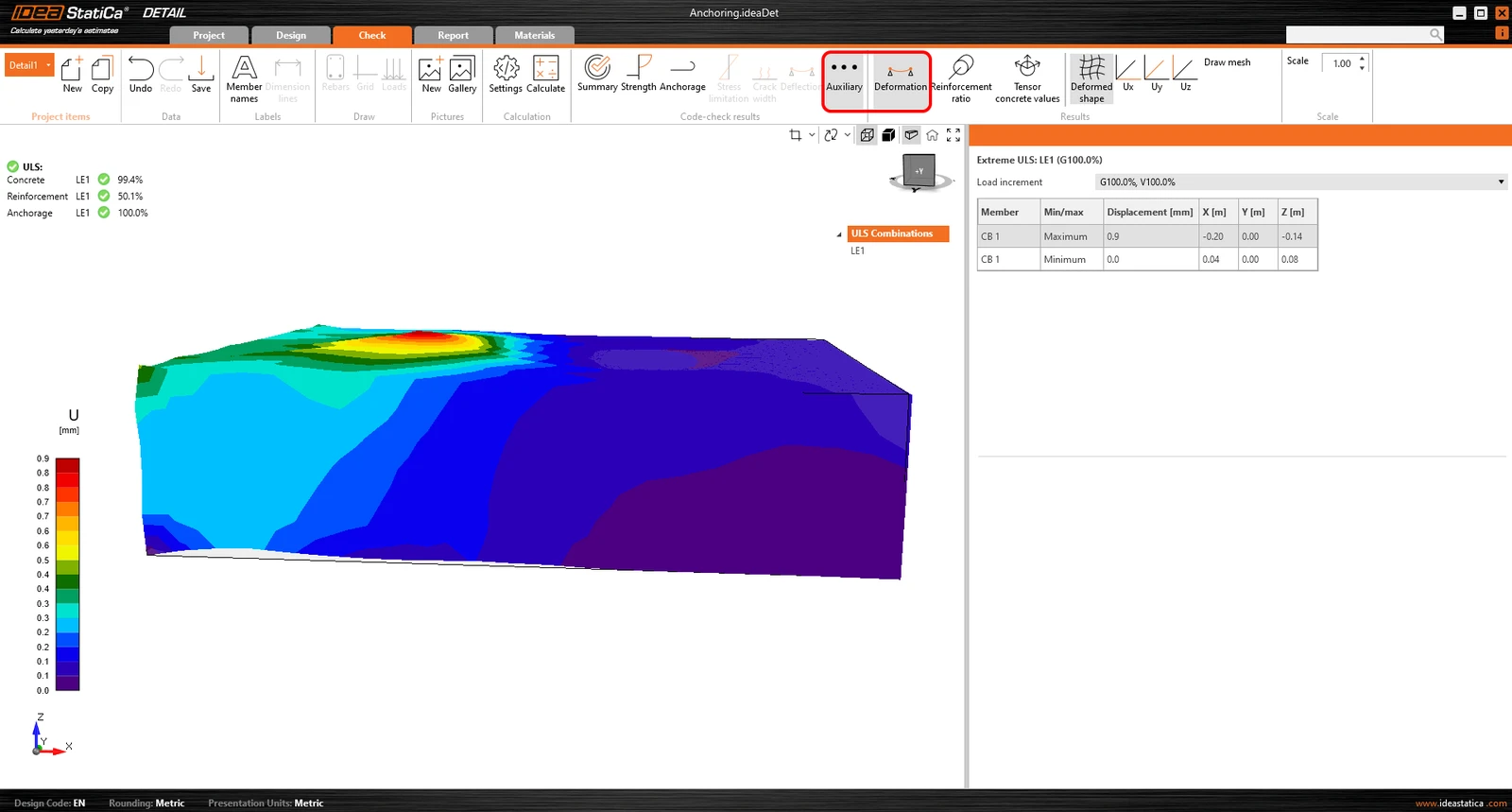
Last but not least, you can view the Auxiliary results in the application – Deformation, Reinforcement ratio, and Tensor concrete values. The first type, Deformation, can display scaled deformations of the ULS non-linear model.
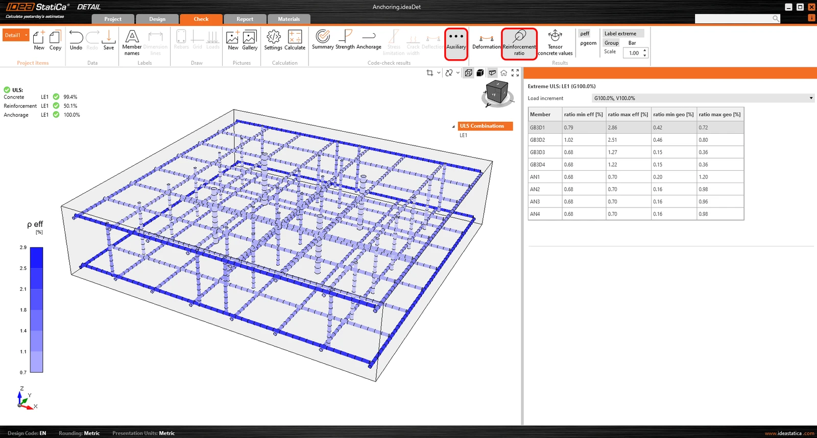
The Reinforcement ratio shows the values used to compute the Tension stiffening effect.
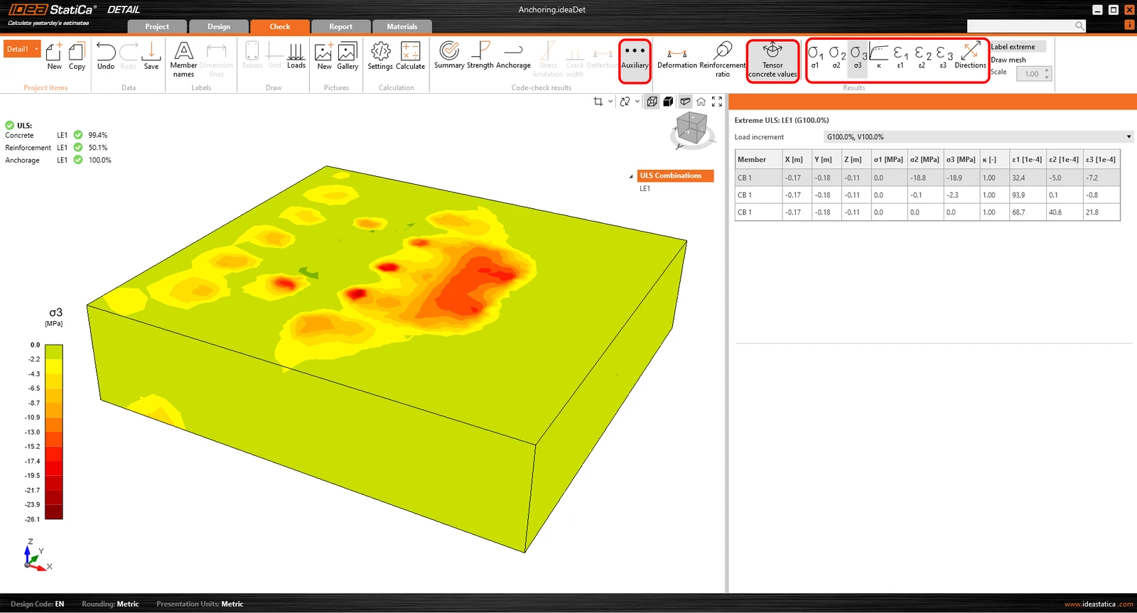
Tensor concrete values allow you to display the intensities of principal stresses in concrete and their direction.
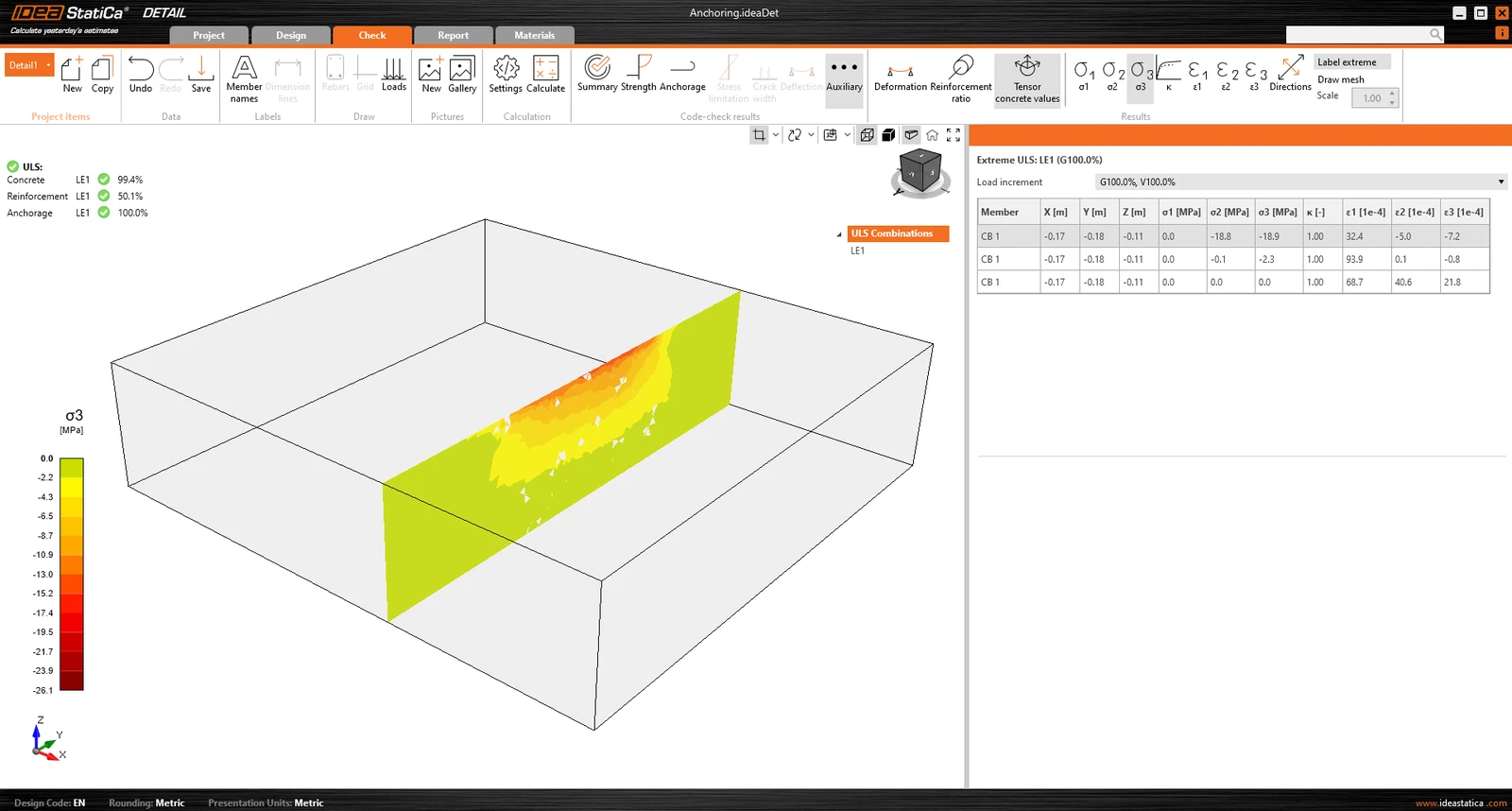
The result sections can also be used.
Investigate model behavior with Section results and Stress check
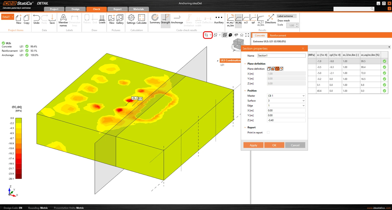
Section Results allow insight into the stresses within the concrete element. It is possible to create any number of sections and in any plane.
For 3D models, there is an option for displaying results for concrete - Section results. To define or modify the sections, you need to use the section button in the view control, which is in the top right corner of the scene.
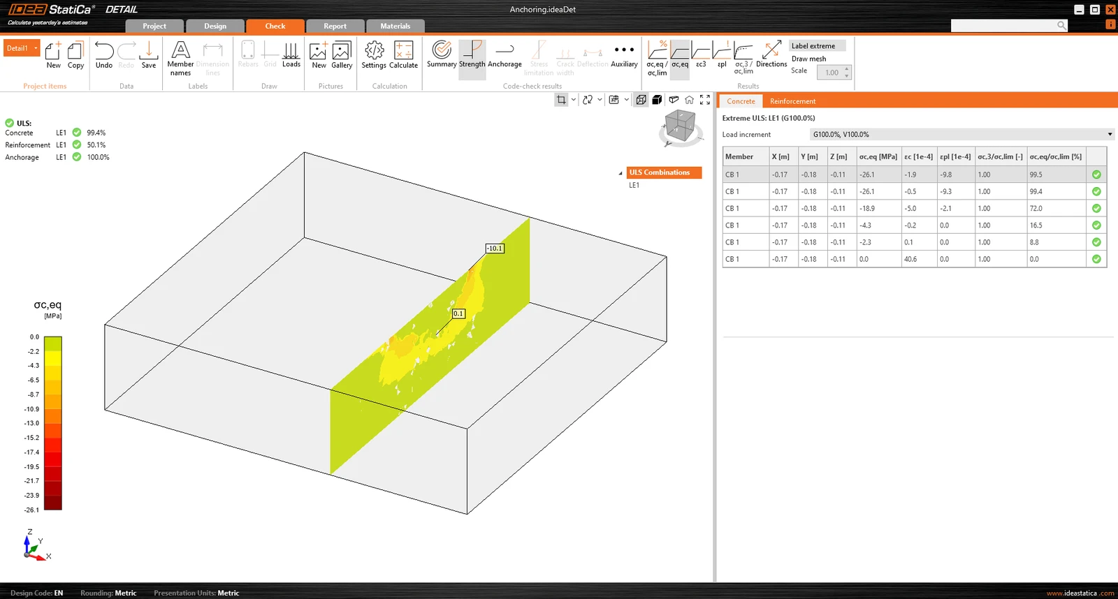
Then you can simply turn on the section button and the results will be displayed via a specified section.
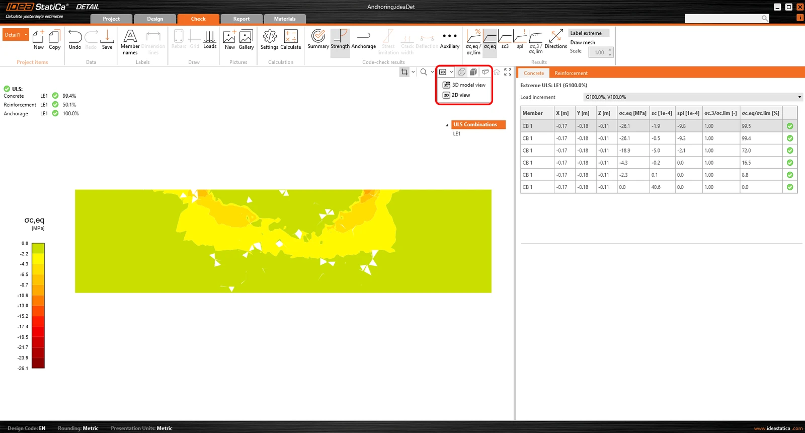
Or there is an option to switch the view from 3D to 2D and for better clarity display the selected section in 2D.
Stress check
For a better understanding of the results and the theory implemented in the 3D Detail, the iconography has been significantly improved. In the "Strength" section, under the concrete stress assessment, you will find new icons and, most importantly, tooltips explaining the basic theory. These tooltips correspond to the theoretical background.
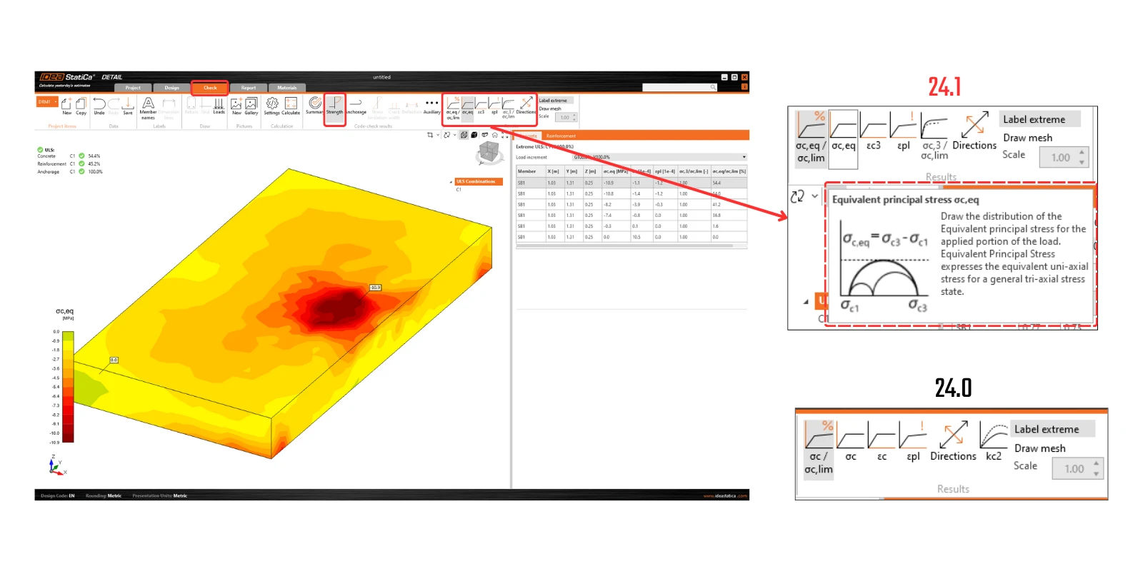
Released in IDEA StatiCa version 24.0.2
Try out the new features of IDEA StatiCa today
Download the latest version for freeReport
Report
As is standard in our applications, all results can be printed to an automatically generated report.
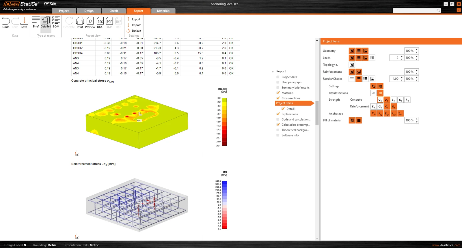
All parts can be edited. It is possible to set a detailed display of the results, a brief display, or no display at all. It is also possible to add user-defined result sections.
You can find more detailed information in the description in Knowledge Base Article: Report in Detail application - the principle is the same for both the 2D and 3D modules.
Bill of Material (BOM)
Bill of Material is an addition to the standard report. It groups bars, illustrates each with its bend dimensions, lists each bar by size and count, and totals the reinforcement weight.
BOM includes
- Reinforcement groups — every reinforcement group in the model, itemized.
- Bar drawings — for each item, a drawing of the bar showing its dimensions, including the individual leg lengths of each bend.
- Bar list — diameters, lengths, and counts for every bar.
- Total weight — the total weight of all reinforcement used in the model.
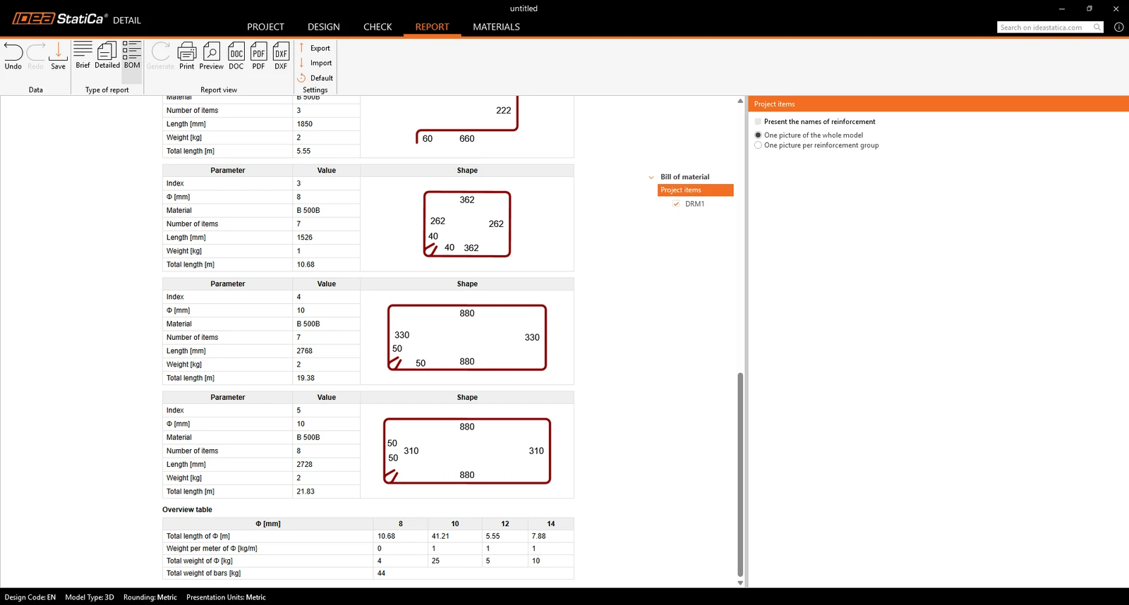
Choosing how reinforcement is pictured
At the head of the bill of materials, you can choose how the schedule depicts the reinforcement:
- One picture of the whole model — shows all reinforcement together in a single view.
- One picture per group — each group of bars is shown separately.
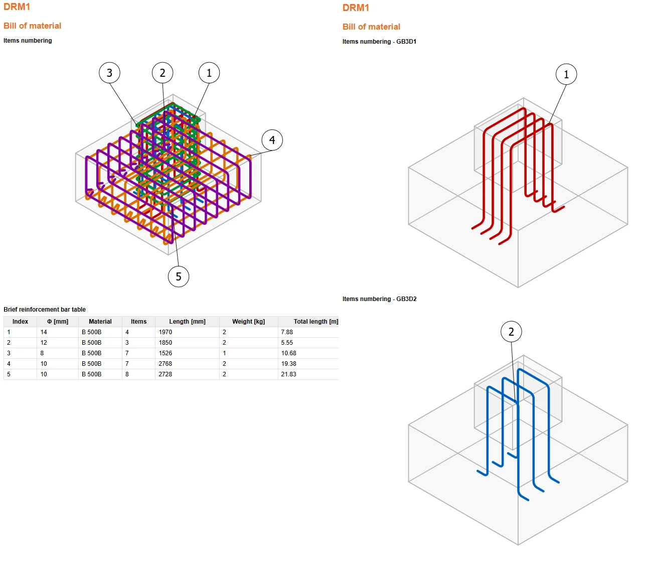
Which to use: the per-group option is the better choice for a dense model. When every bar is shown in one view, groups overlap, and it becomes hard to tell which item a given row in the schedule refers to. Splitting the view into one picture per group keeps each row of the schedule paired with an unambiguous picture.
Exporting to DXF
The reinforcement list can be exported to DXF, so the schedule can be brought into a CAD environment and used directly in drawing production instead of being retyped.
Bend dimensions are preserved in the export — the leg lengths of each bend remain readable in the DXF — which is what makes the exported list usable as a bar-bending schedule.
Scope and known limitations
- DXF export scope: the DXF export covers the reinforcement list only. The 3D views themselves are not exported in this release.
- Not a full drawing set: this feature is a bill of materials for the reinforcement, not a full drawing set. It delivers quantities and an itemized bar schedule — not detailing drawings.
Note: Released in IDEA StatiCa version 26.1.