1 New project
Start with launching the IDEA StatiCa Connection. Create a new project by selecting a starting template closest to the desired design, filling in the name, and choosing AISC design code and default steel grades as shown below.
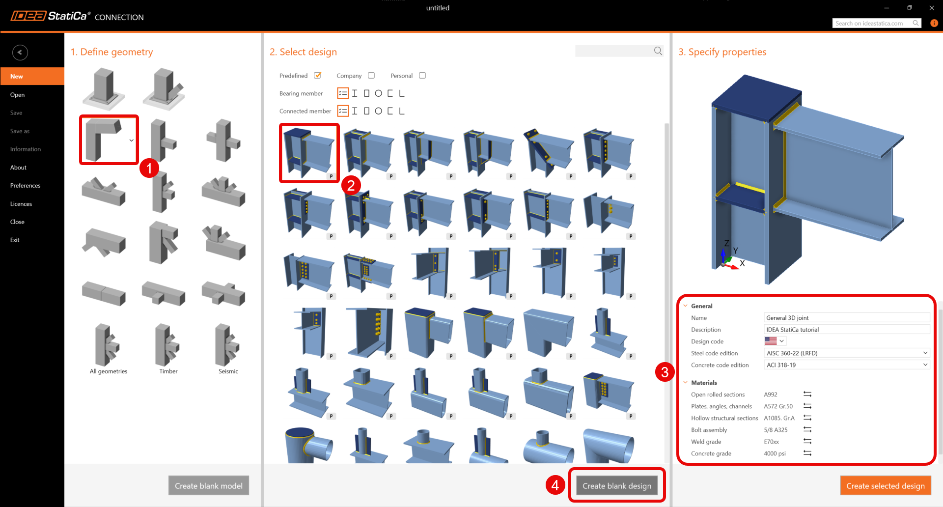
Since you work under the AISC code, set the imperial units (see How to change the system of units).
2 Geometry
Two beams were automatically added as part of blank design template.
Member C
You will create a general cross-section for the column member. To do that, select Welded, Composed tab and click on the General steel cross-section.
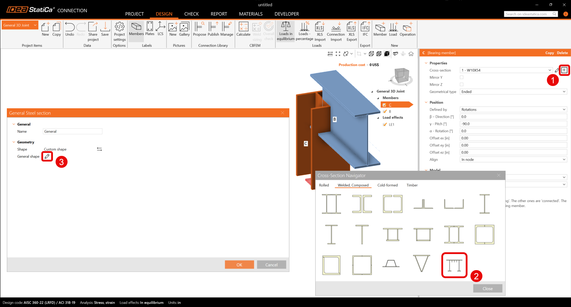
The General cross-section editor is opened, and you can start composing the cross-section by selecting the I-sections in the Cross-section Navigator.
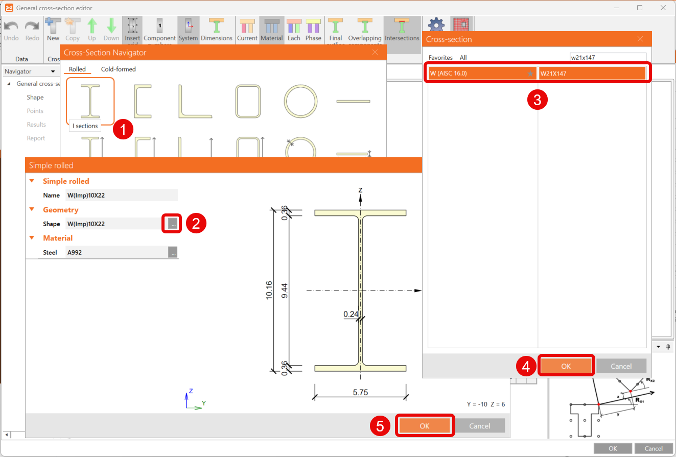
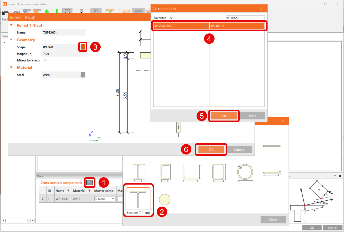
Then continue by clicking on the icon Add new entity and selecting the Sections T (I-cut). The Rolled T (I-cut) window is opened, and you can edit the shape.
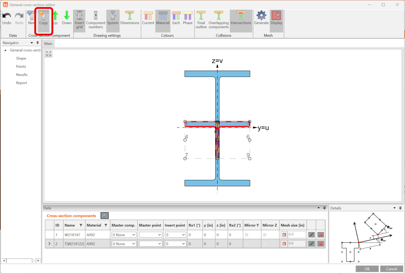
Make a copy of this entity by clicking the Copy icon in the upper ribbon.
Next, move and rotate the added T-shaped entities to design the whole cross-section by editing of values in the Cross-section components tab as in the figure below.
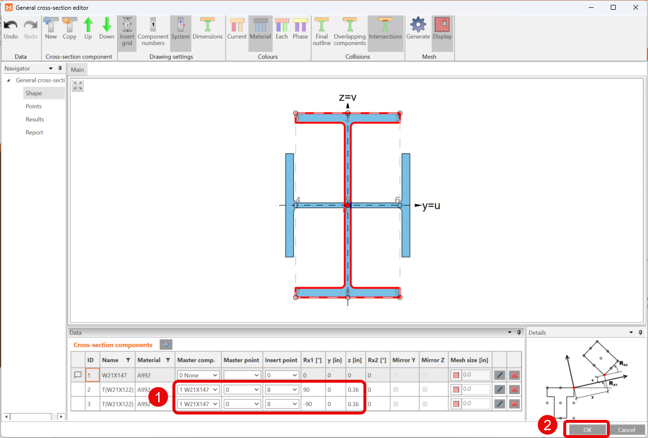
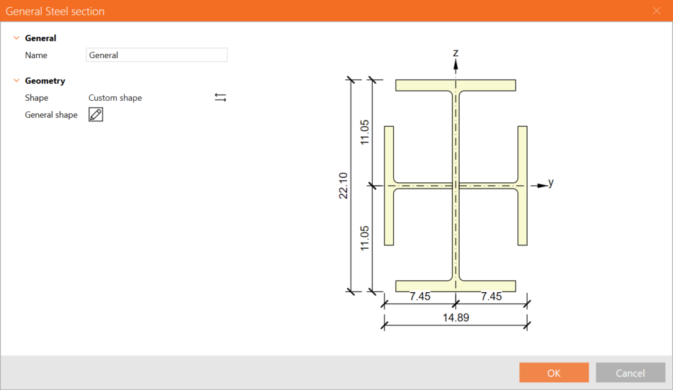
You now have the final design of the cross-section for member SL.
For further information, see How to create and use a custom cross-section.
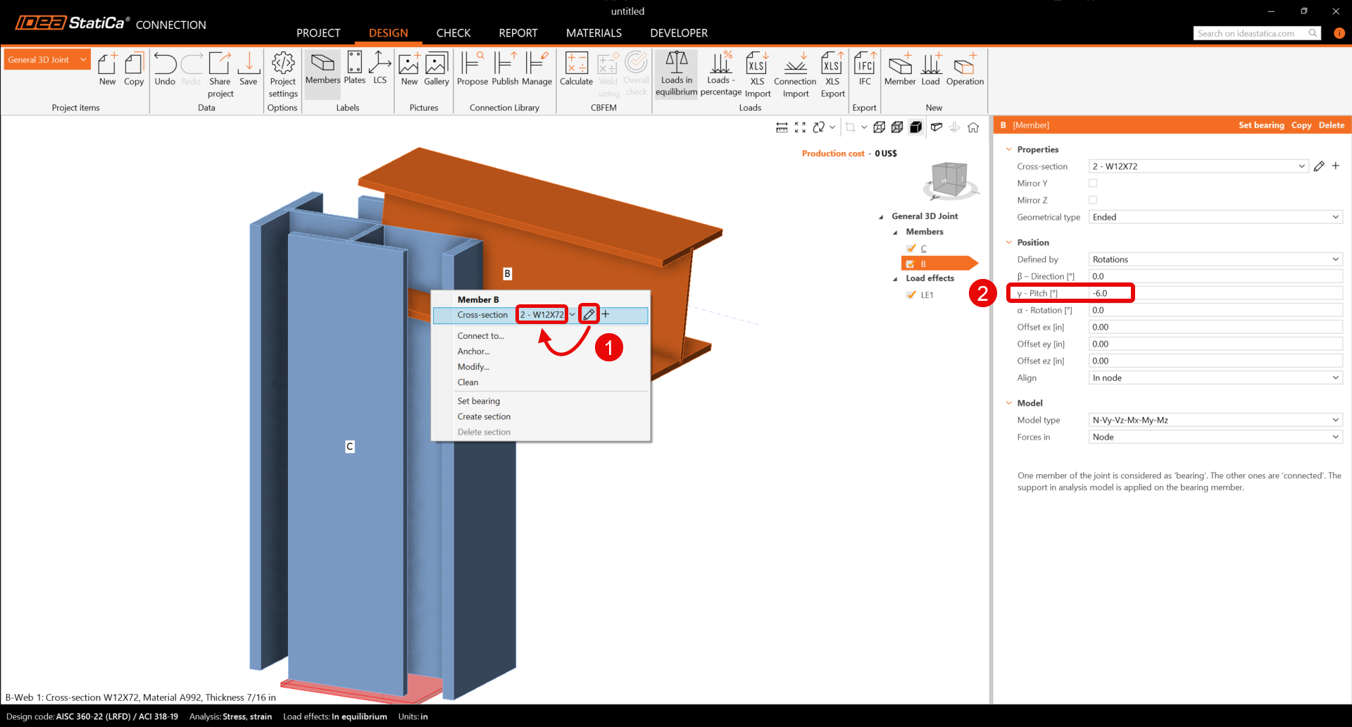
Member B
Start with Right-click on the beam B and set the cross-section to 12X72 from the W (AISC 16.0) library.
You will also have to change the member B properties.
Member M3
On the upper ribbon, select the Member icon to add the new member M3. Set the cross-section to W8X21 from the W (AISC 16.0) library on beam M3.
You can go on and change the member M3 properties.
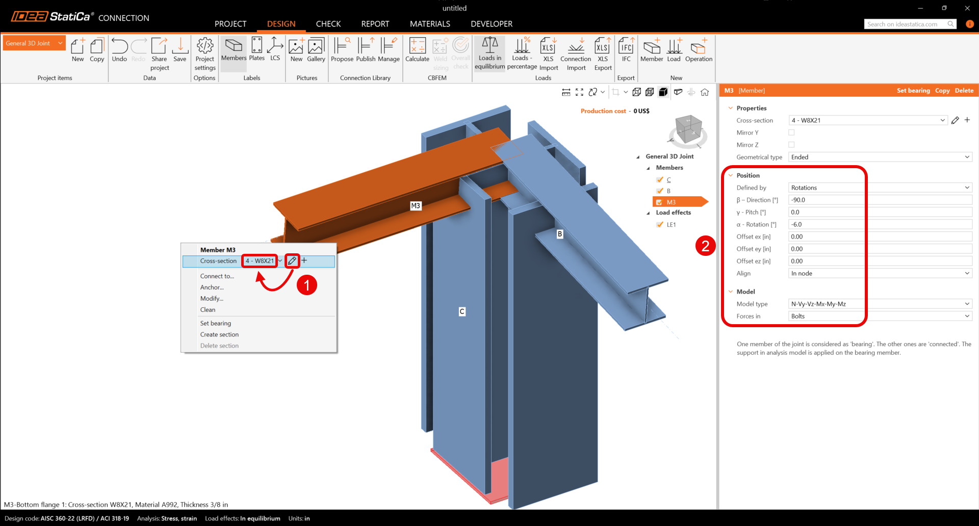
For further information about the property Forces, see How to define load position.
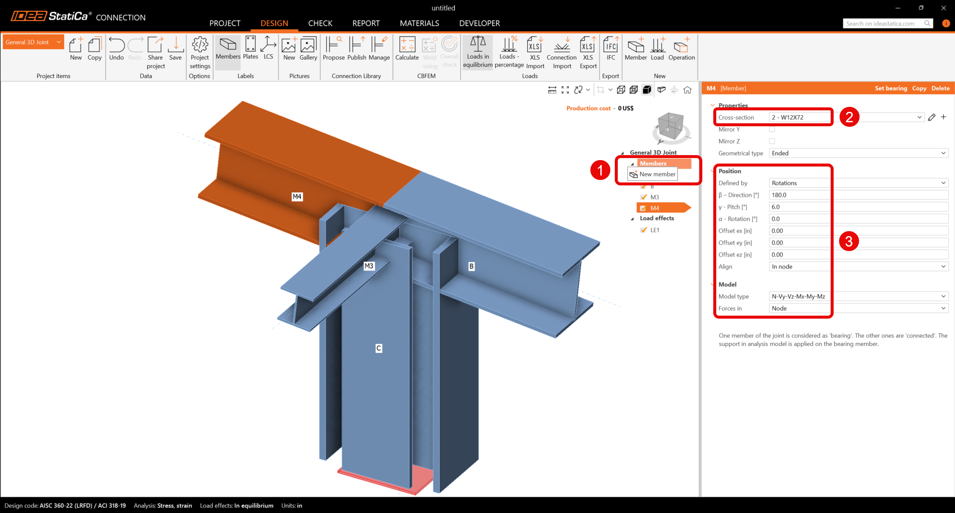
Member M4
Click the right mouse button at the Members row in the tree of entities in the 3D scene. Choose the New member command from the context menu. Continue and change the member M4 properties.
Member M5
Add another member, set its cross-section to L4X4X3/8 from the L (AISC 16.0), and update properties.
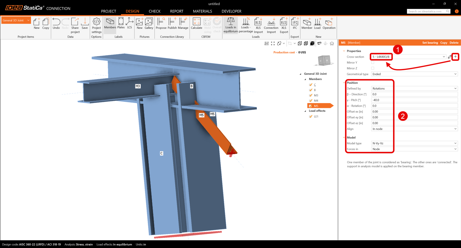
Check the final geometry of members.
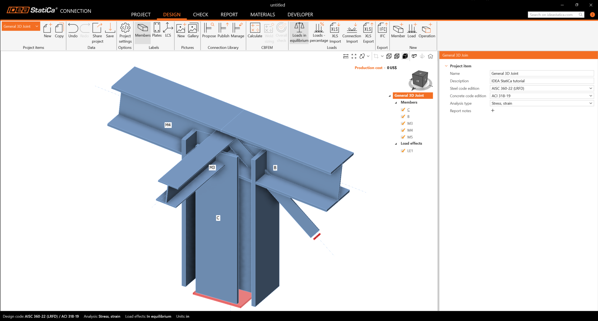
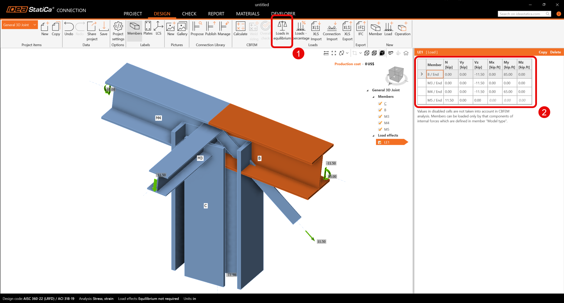
3 Load effects
One load effect was automatically added. Input the values of internal forces into the chart and turn off Loads in equilibrium. More load cases can be added.
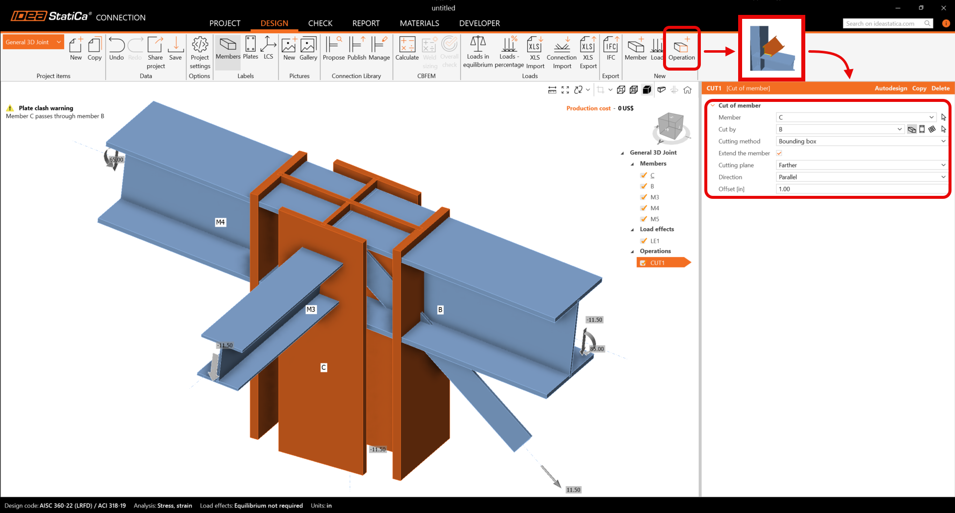
4 Design
Add a new one by the command new Operation at the top ribbon. First, select the Cut of member operation to extend the column. Now change the properties of the operation CUT1. Follow the picture below.
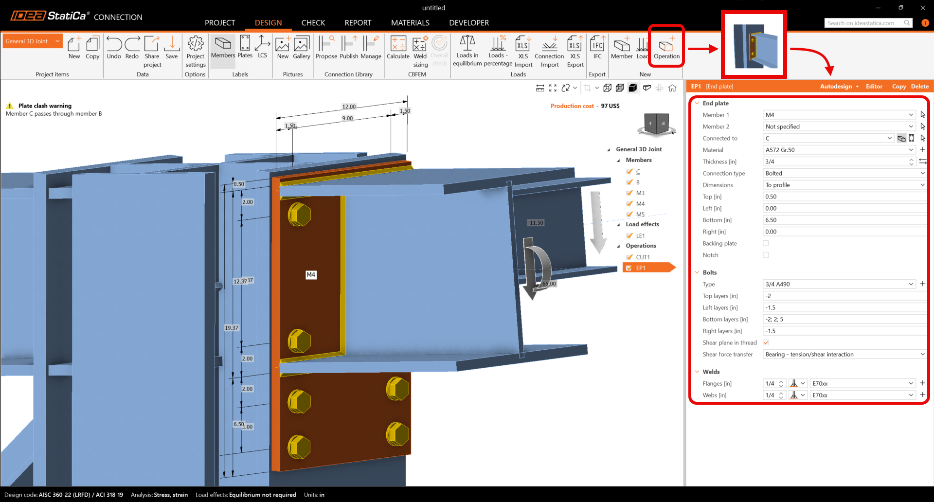
Go on and add the next Manufacturing operation. Now, select the End Plate and change the properties of the operation EP1.
Copy operation EP1. With the right mouse button, click on the EP1 and choose Copy.
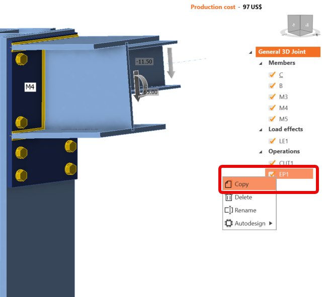
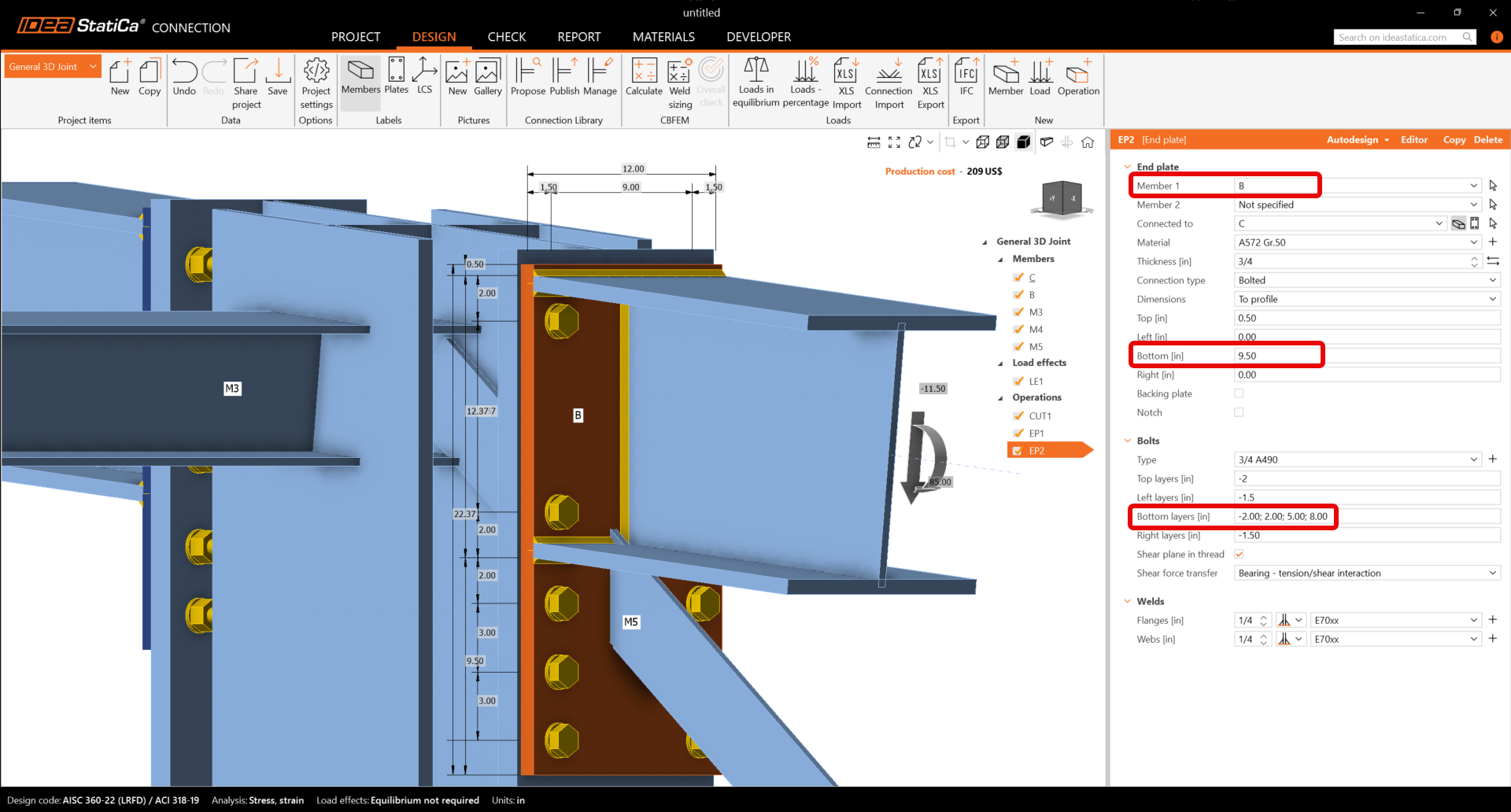
Now you have to set the correct properties of EP2.
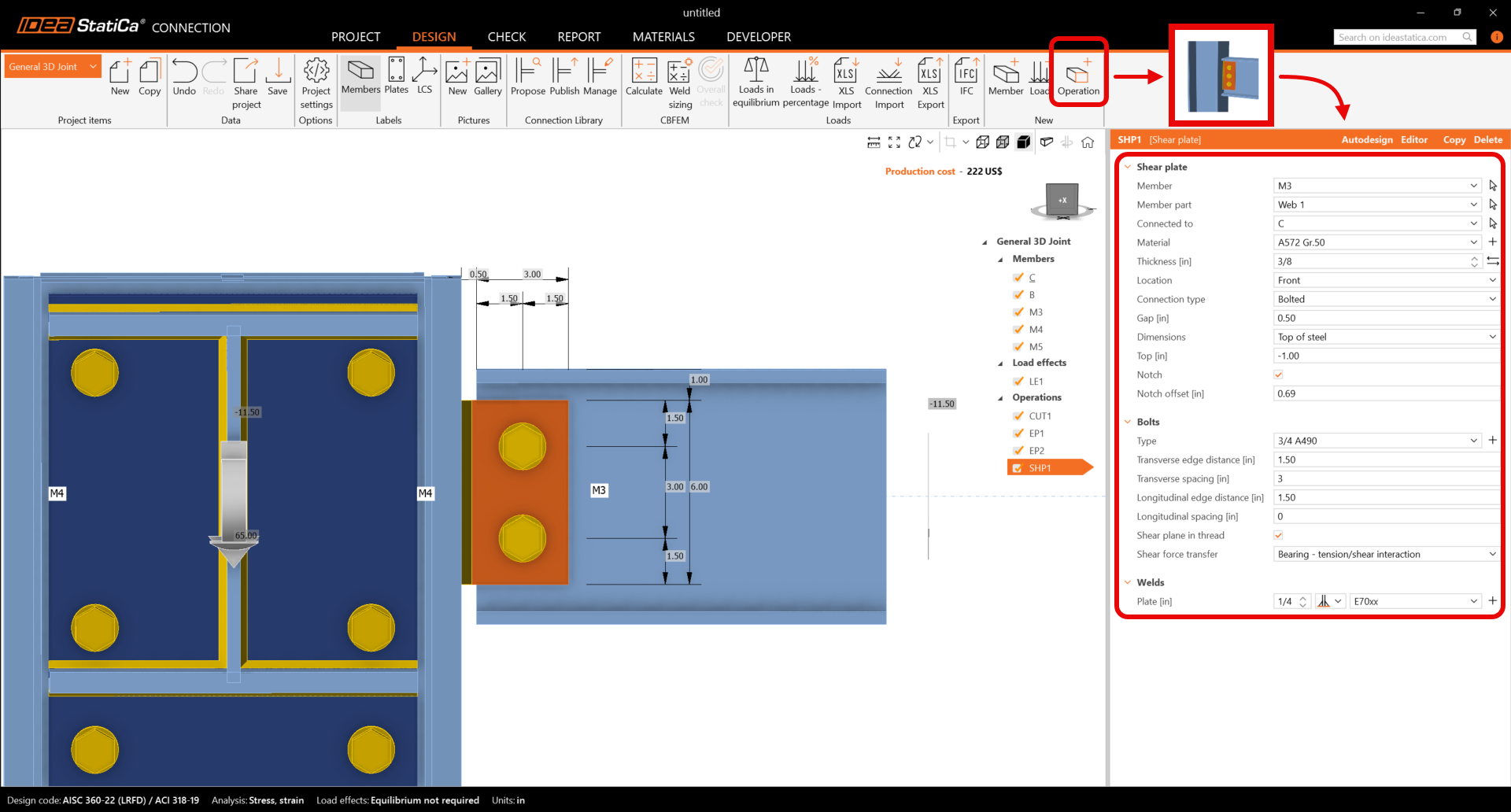
Continue and input a Shear plate and change the properties of the operation SHP1. Follow the picture below.
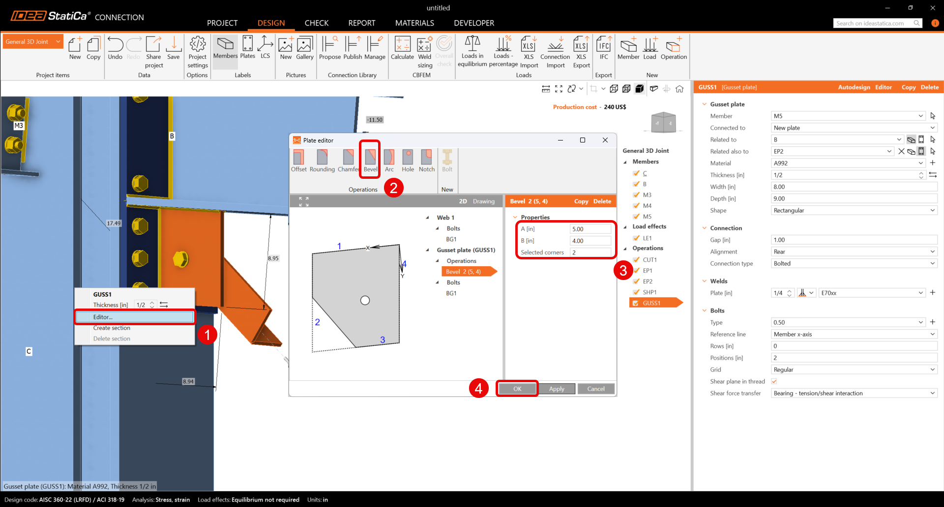
Finish the design by adding a Gusset plate operation and set the parameters for GUSS1.
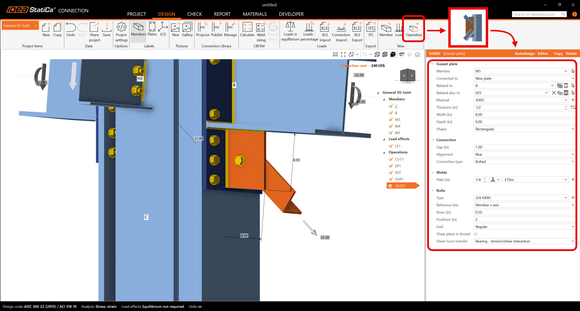
Finally, edit the gusset plate shape. With the right mouse button click on plate GUSS1 in the 3D scene and choose Editor. Inside the plate editor, modify the gusset plate by the input of a Bevel.
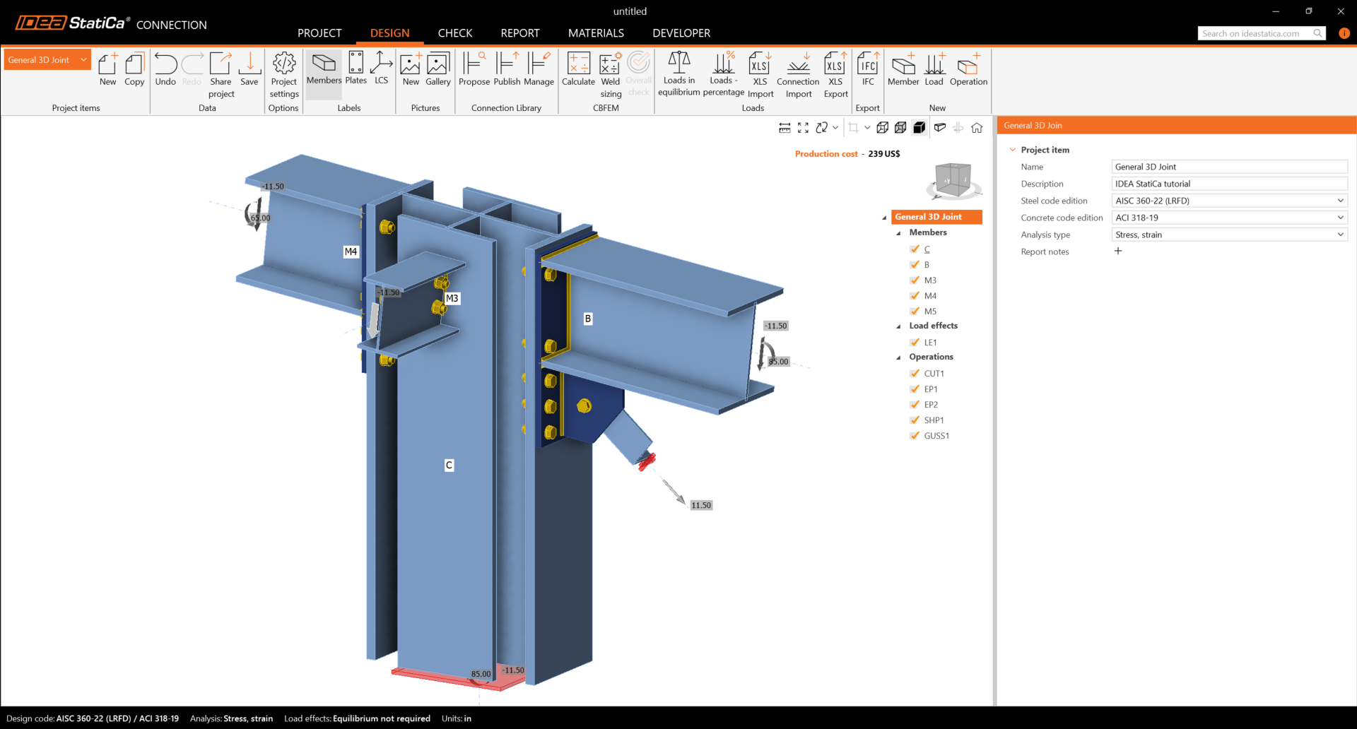
Check the final design of the joint.
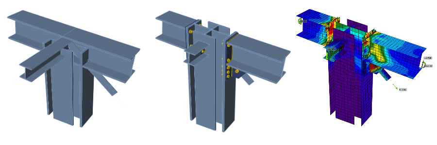
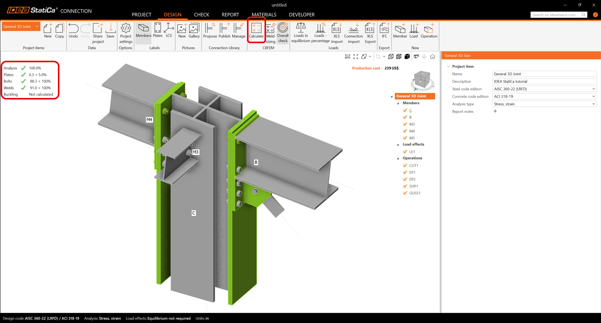
5 Calculation and Check
You can start the analysis by clicking Calculate in the ribbon. The analysis model is automatically generated, the calculation is performed, and you can see the Overall check displayed together with basic values of check results.
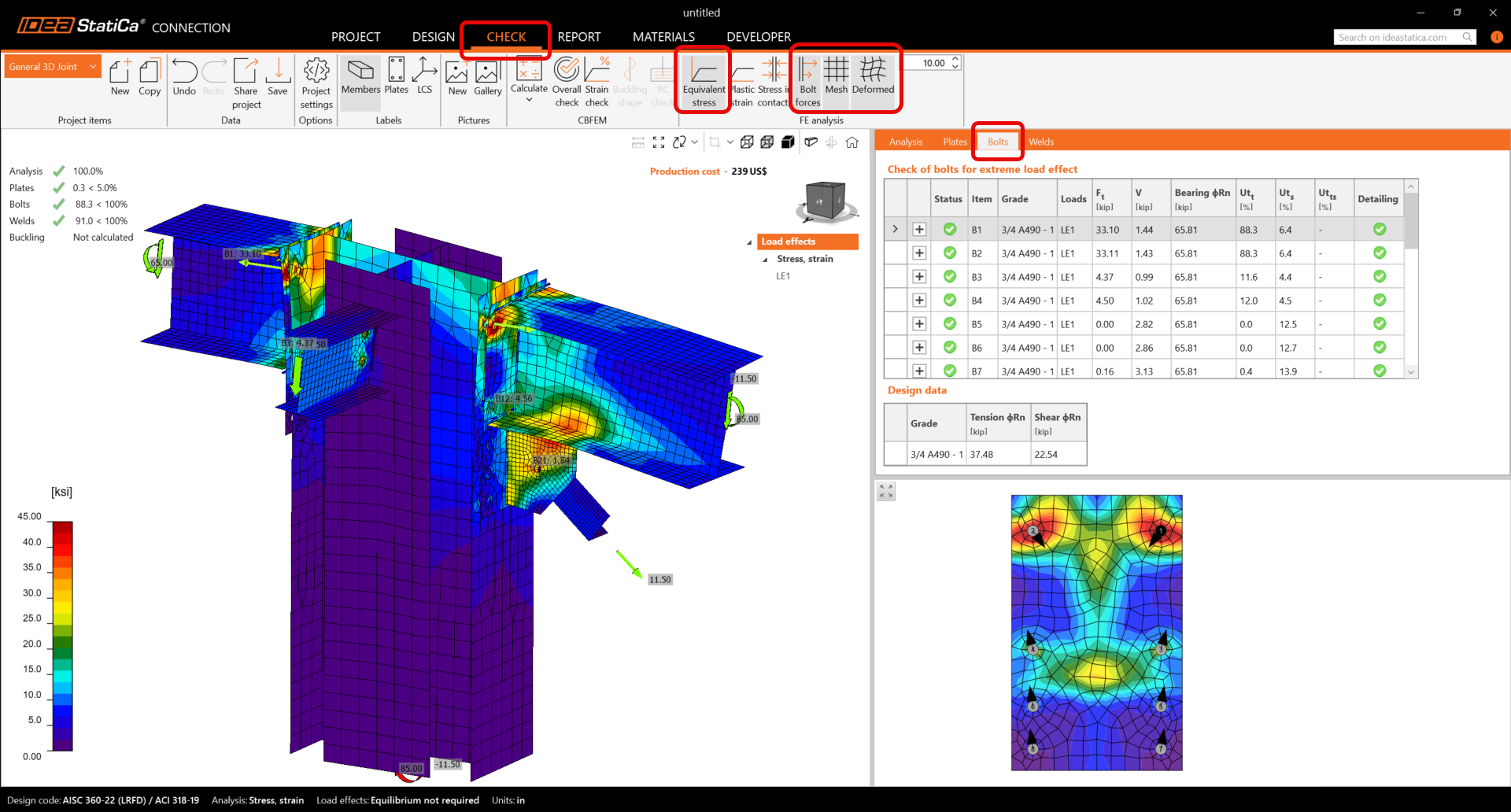
Go to the display tab Check, and activate Equivalent stress, Bolt forces, Mesh and Deformed from the ribbon to get a full picture of what is happening in the joint.
Values of bolt checks and forces together with check equations are displayed in the table Bolts, equally, there is a tab for welds, etc.
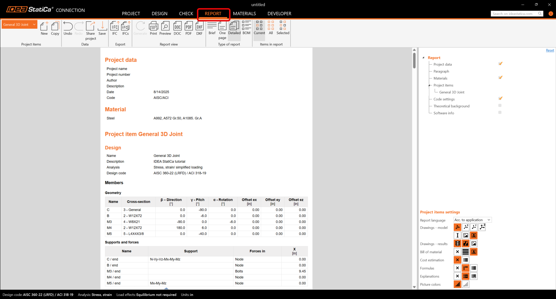
6 Report
At last, go to the tab Report. IDEA StatiCa offers a fully customizable report to print out or save in an editable format.
You have designed, optimized, and code-checked a General 3D joint according to AISC.
Learn how to use IDEA StatiCa effectively with our self-paced e-learning courses
Start learning


