1 New project
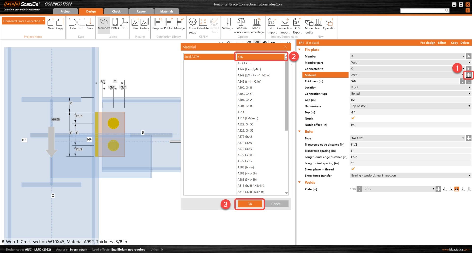
To begin, launch IDEA StatiCa and select application Connection. Create a new project by selecting a starting template closest to the desired design, filling in the name, and choosing the design code and default material properties – A992.
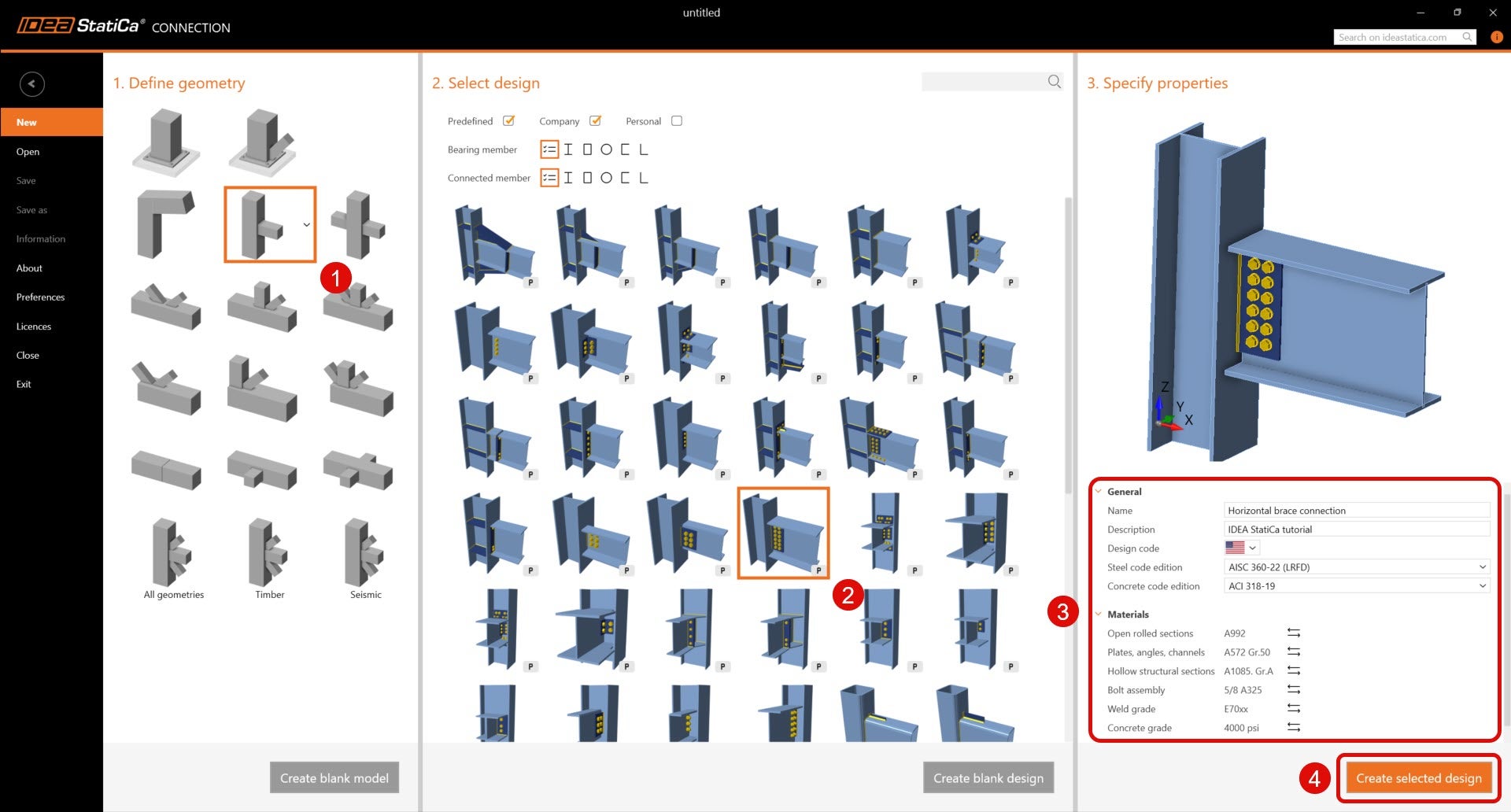
Since this project follows the AISC code, let's proceed by utilizing imperial units (see How to change the system of units).
2 Geometry
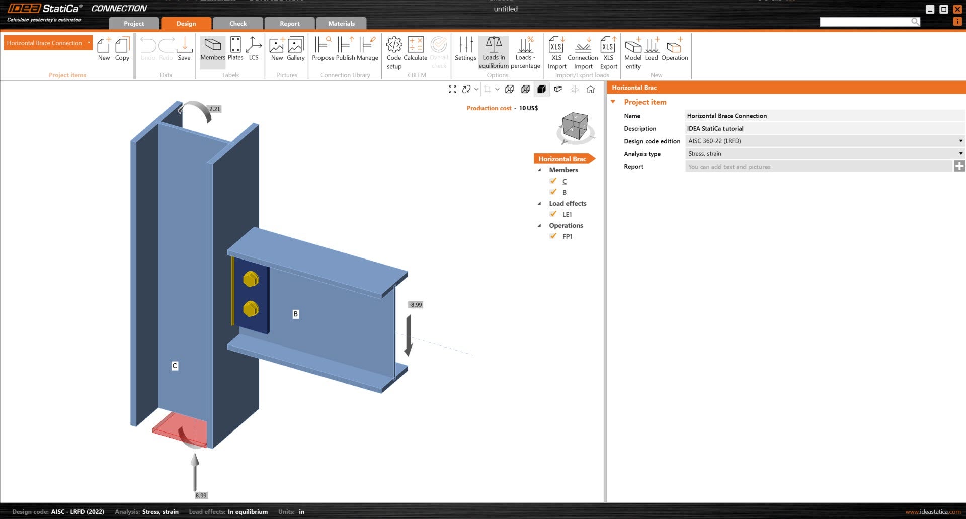
A column and beam with shear connection was automatically added onto the design.
First, change the cross-section of the column. New cross-section is W12x96.
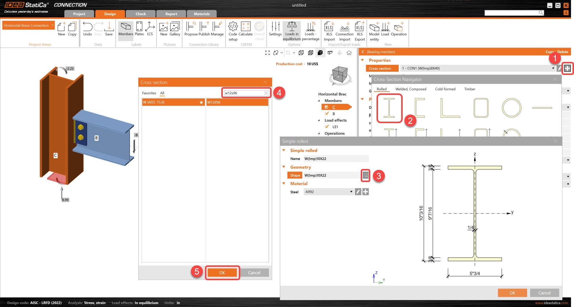
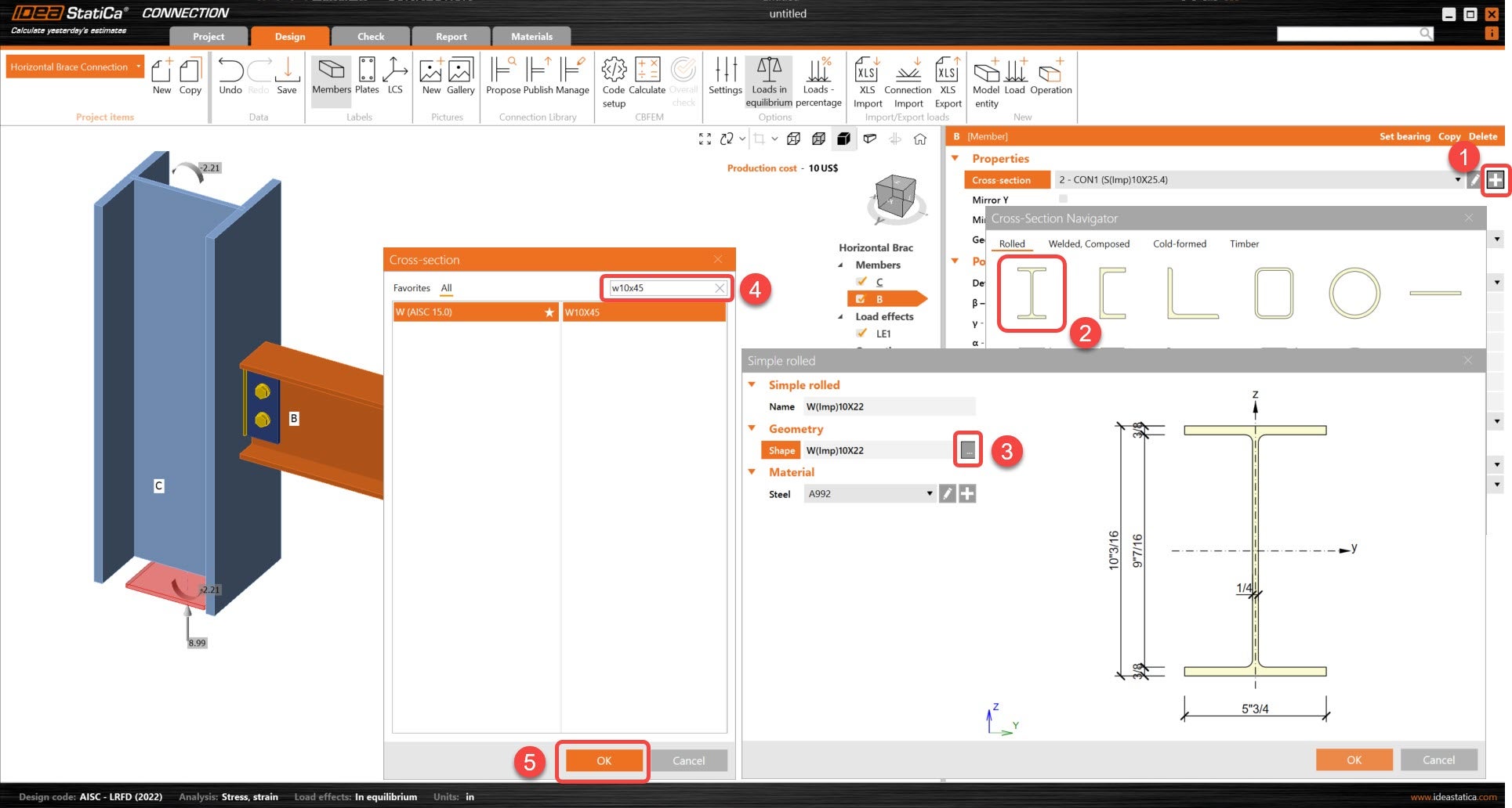
Next, change the cross-section of the beam. New cross-section is W10x45.
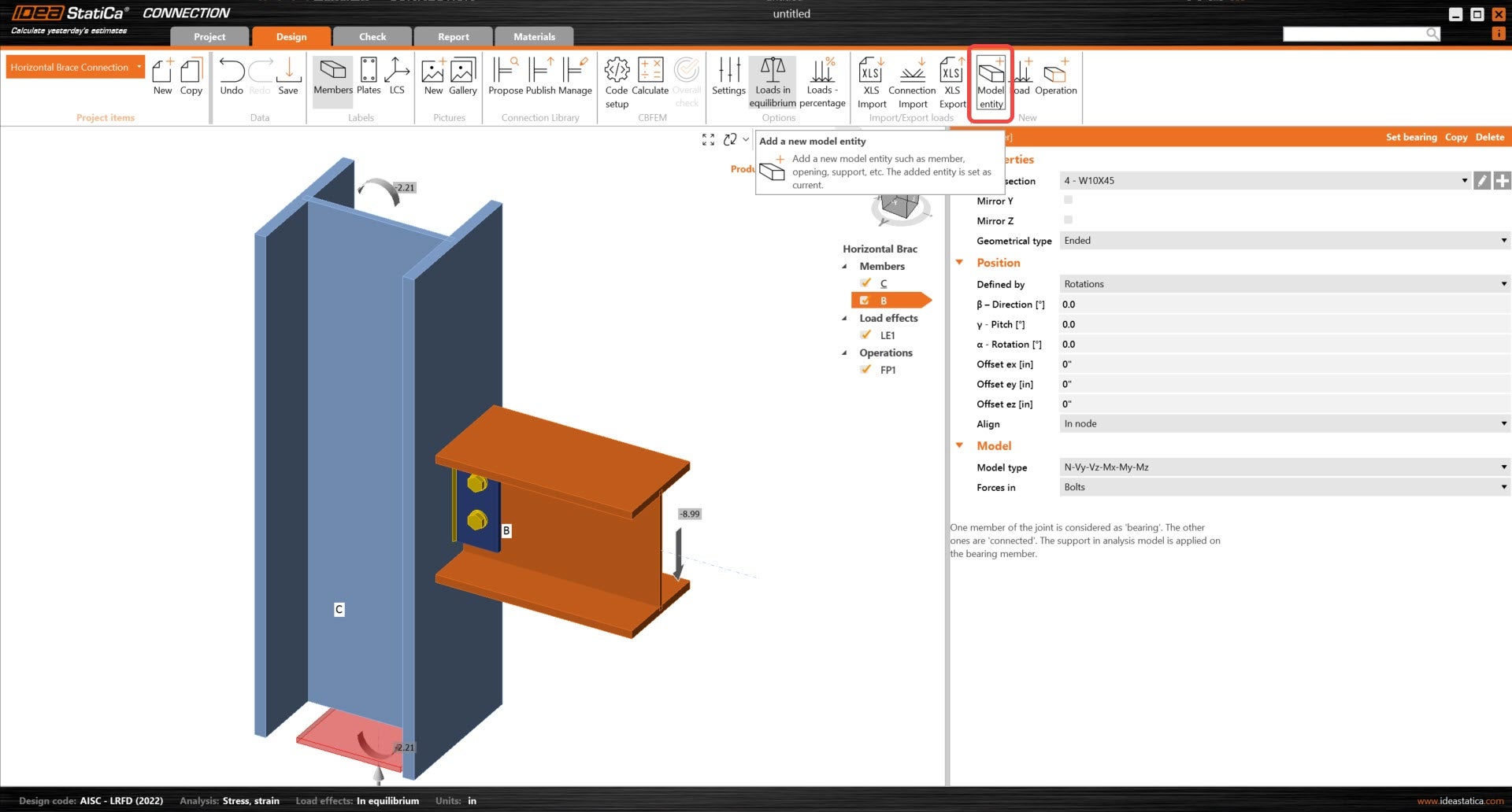
Then add two new members.
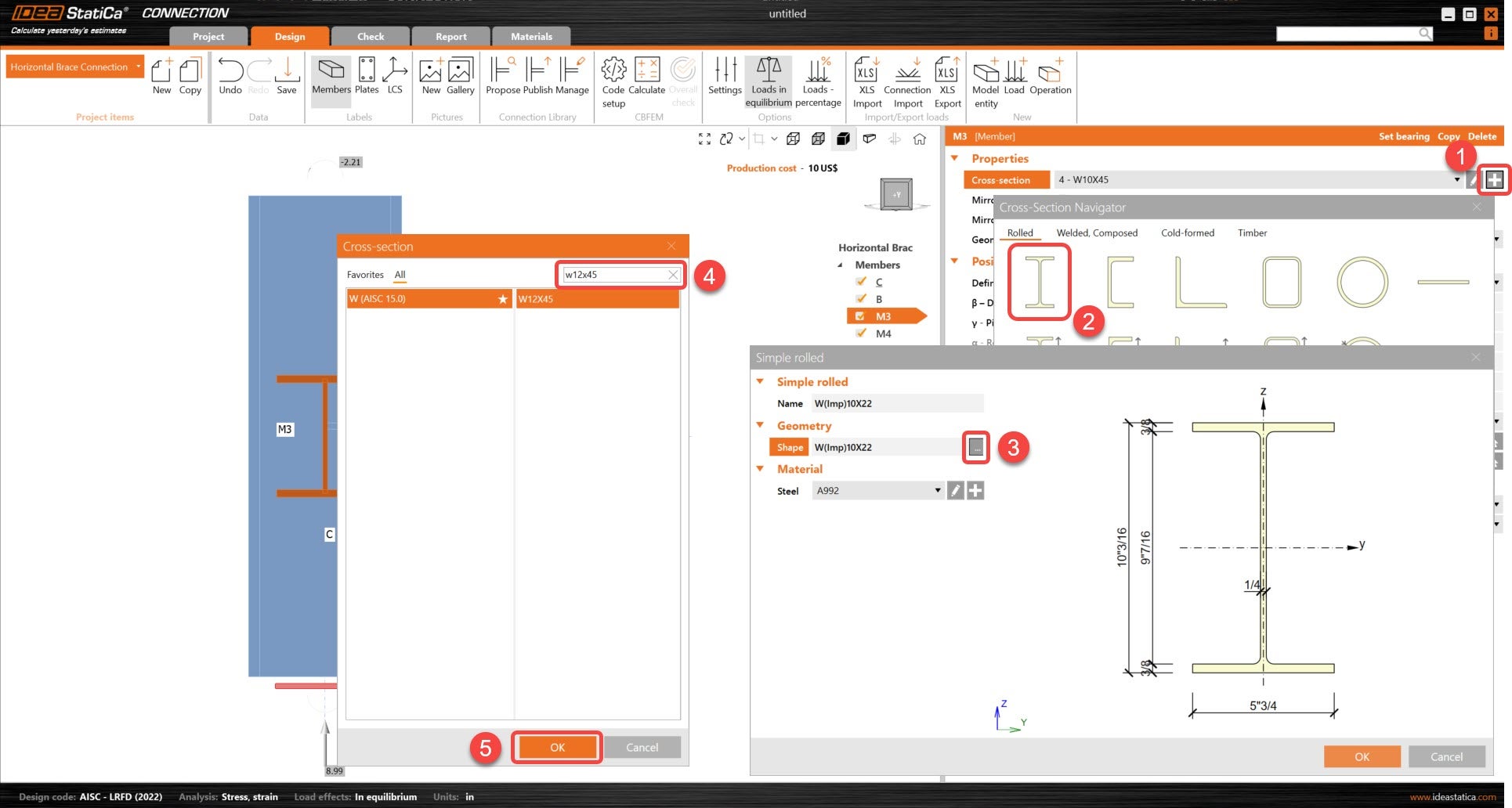
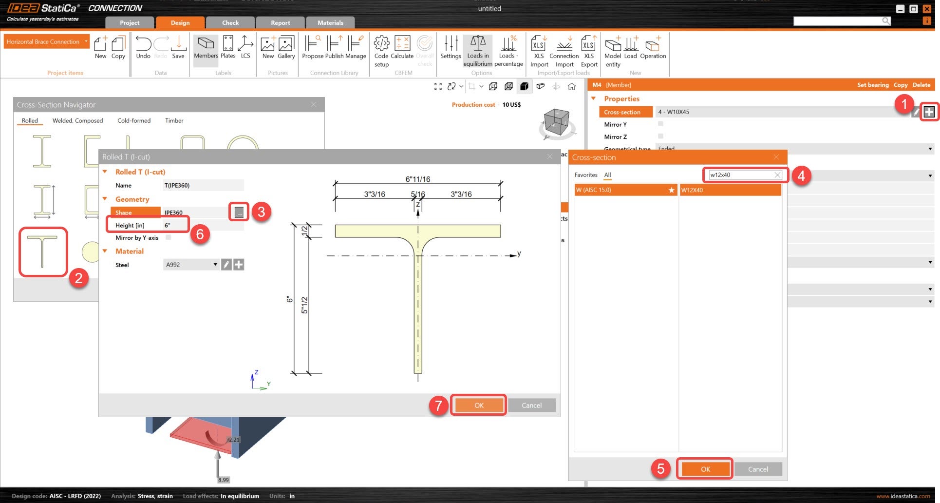
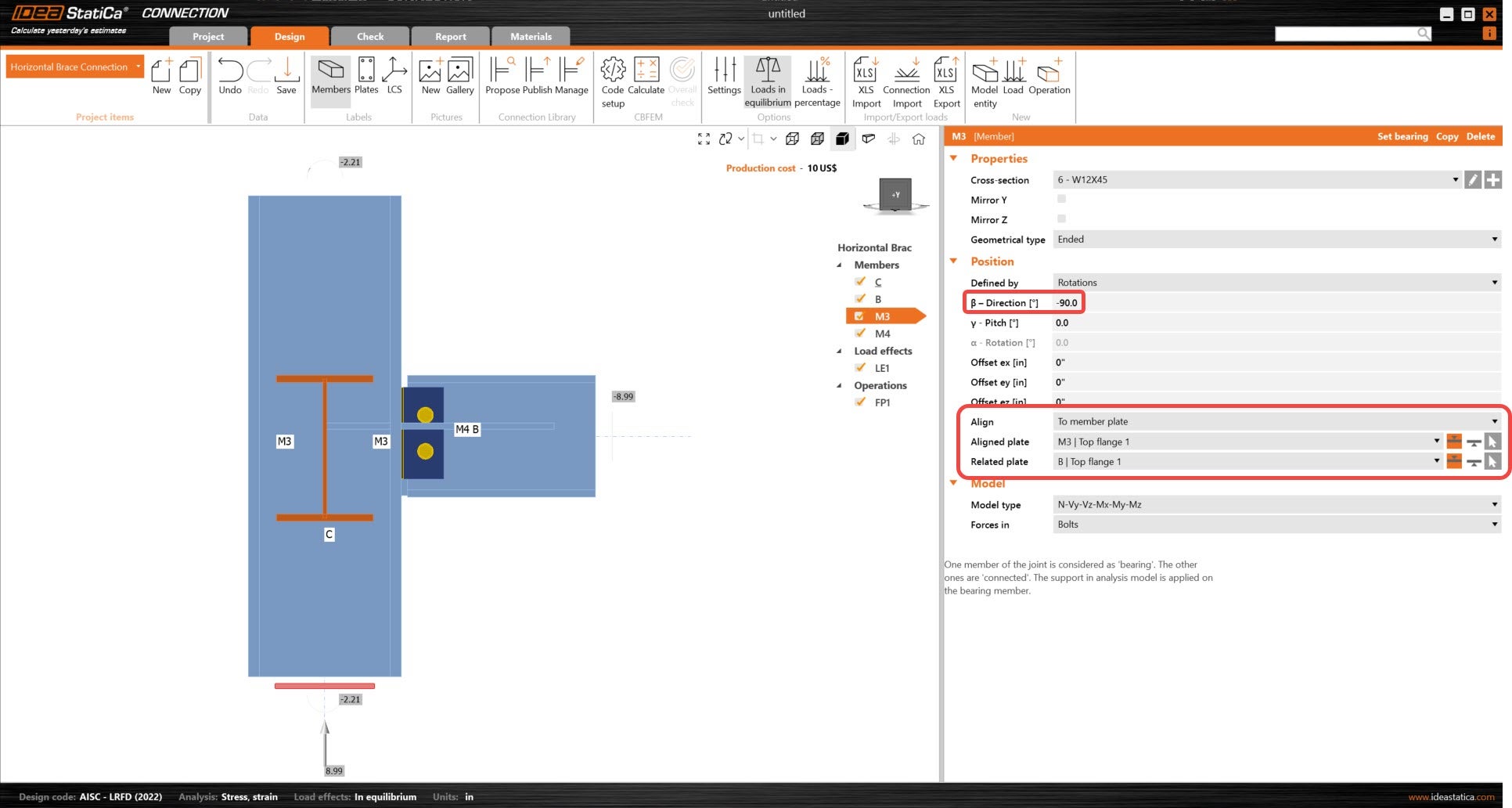
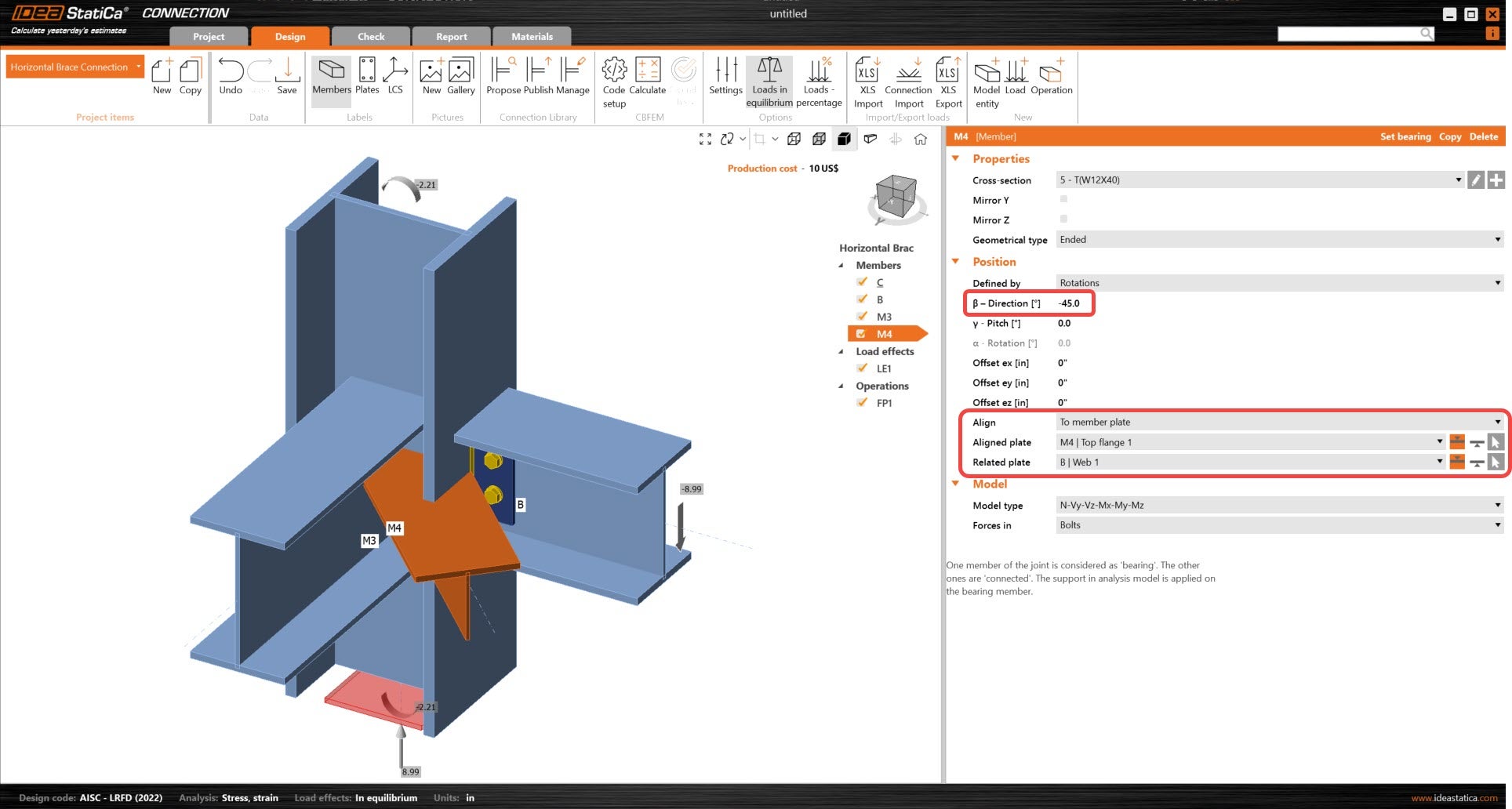
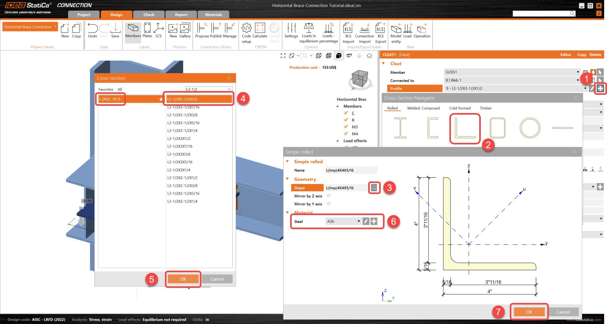
Change the cross-sections of the two new members. For M3, new cross-section is W12x45. For M4, the new cross-section is T-section from a W12x40.
Adjust the position parameters of both M3 and M4. Their directions and alignment will be updated so that the full geometry can be complete.
3 Load effects
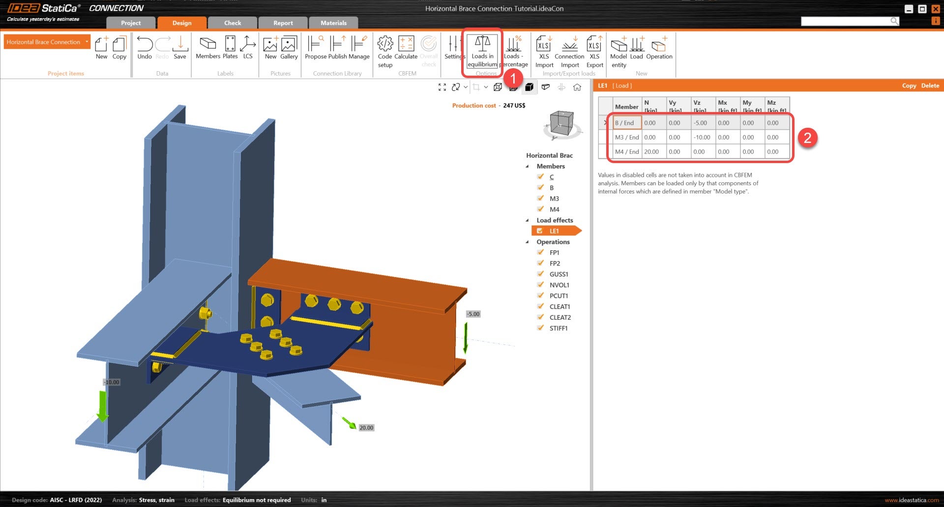
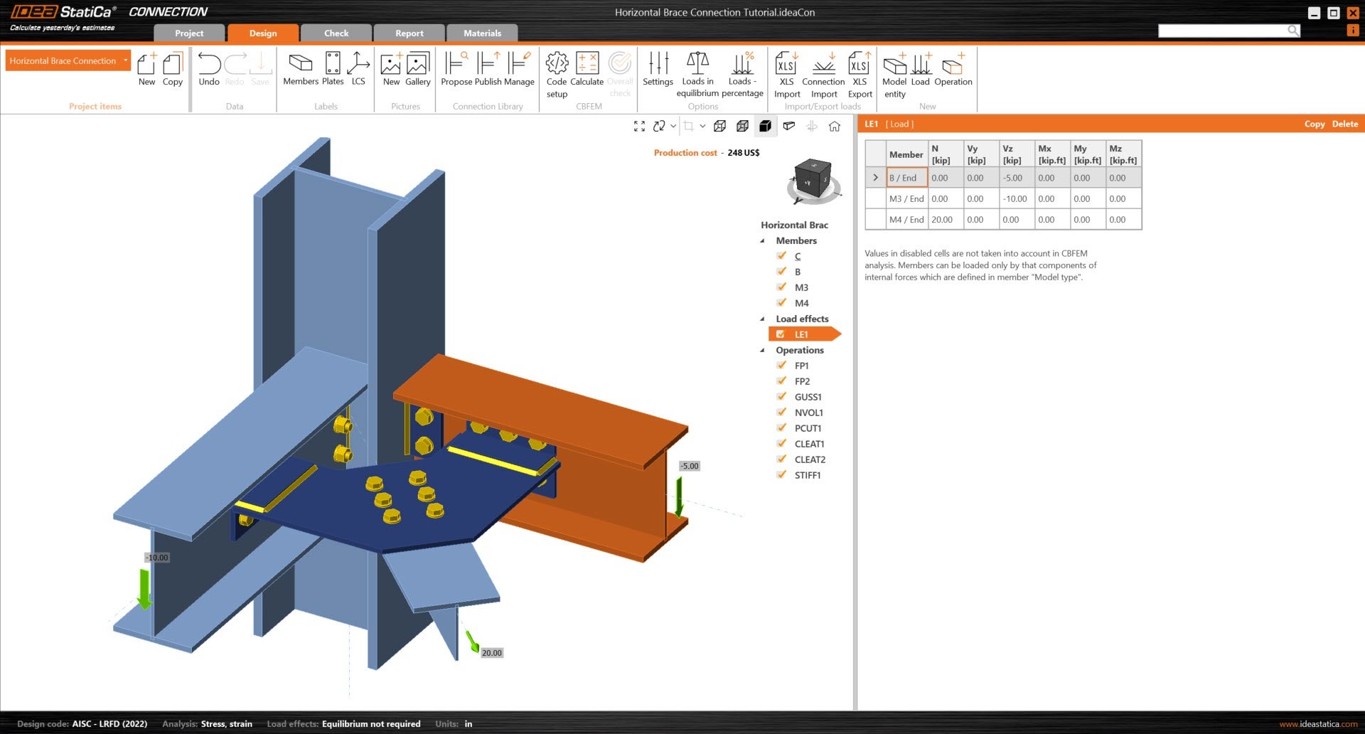
Remove the default load effects that are present in the model.
Turn off Loads in equilibrium and input the new values of internal forces into the chart. More load cases can be added.
4 Design
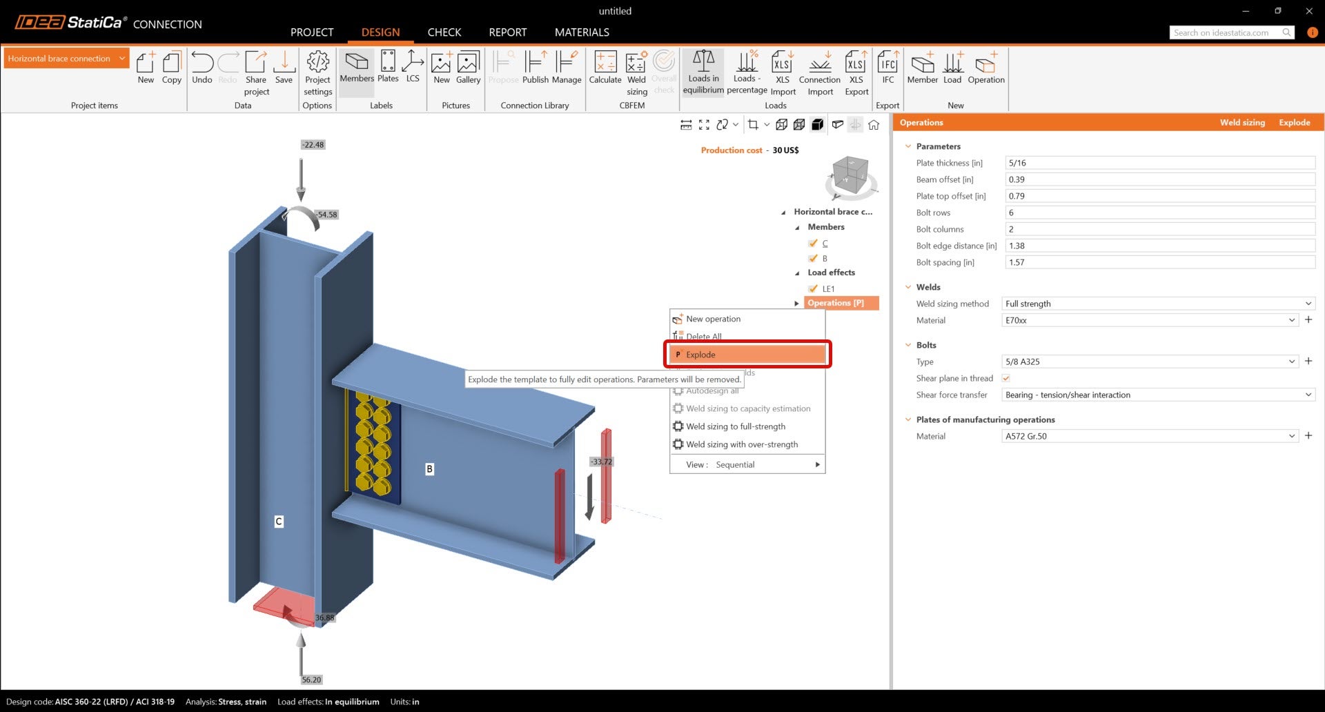
Before the connection can be modeled, make sure to "Explode" the parametric template. Right-click on the Operations (P) label and select "Explode" as shown below.
The manufacturing operation Fin plate was already created. Just update some of its properties.
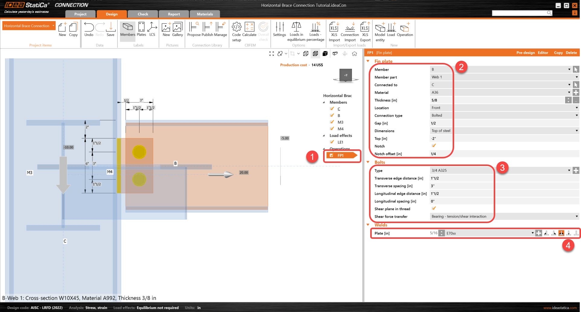
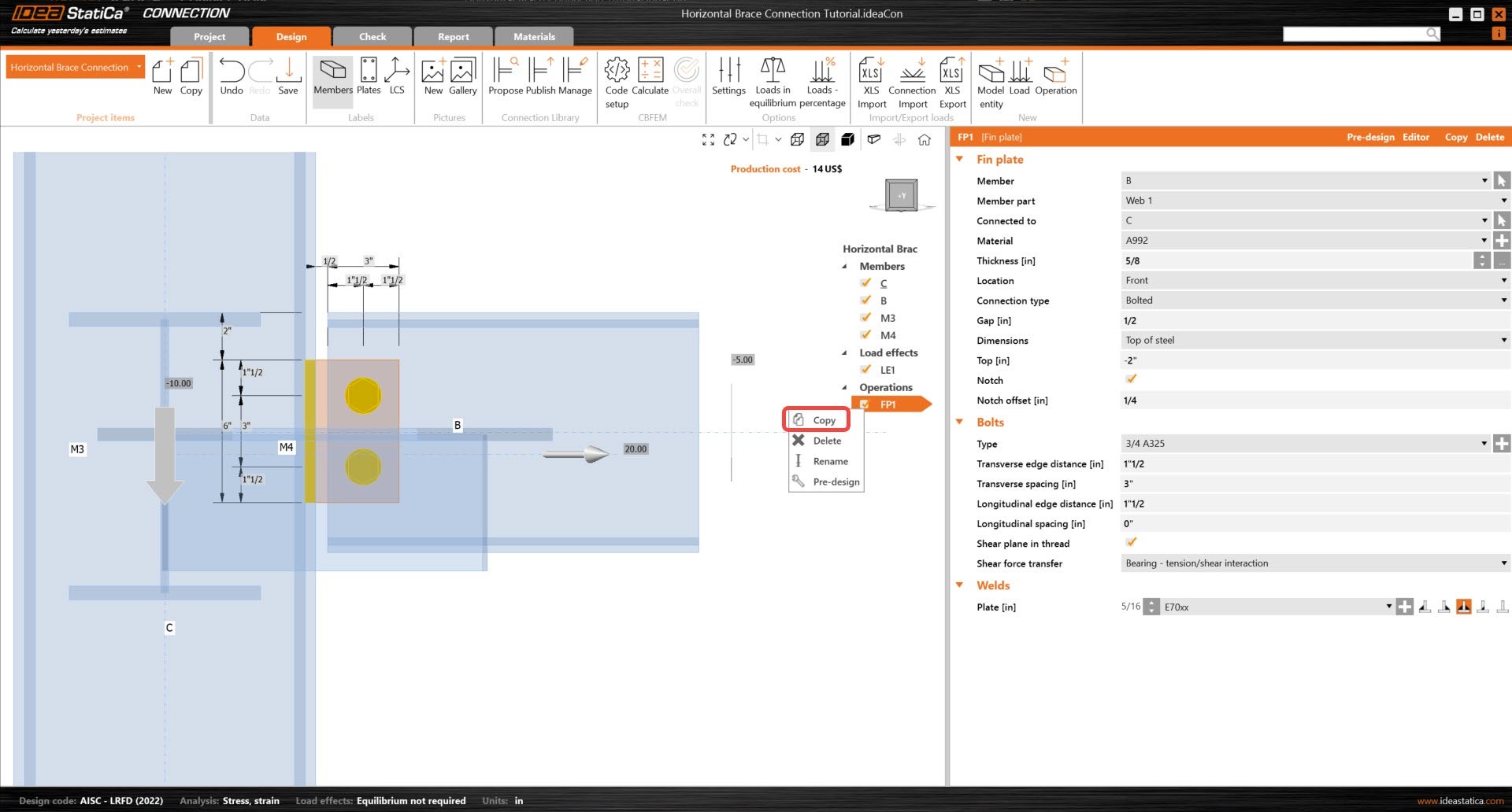
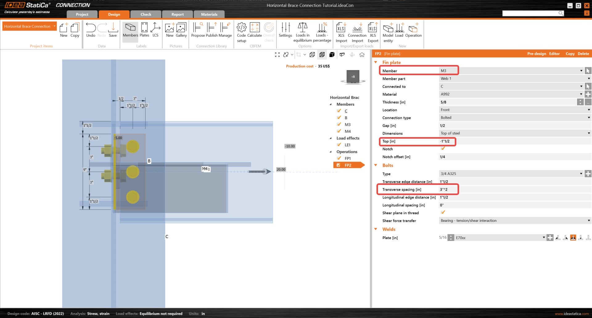
Right click on the operation FP1 and copy the operation, then update the following properties so that it relates to member M3.
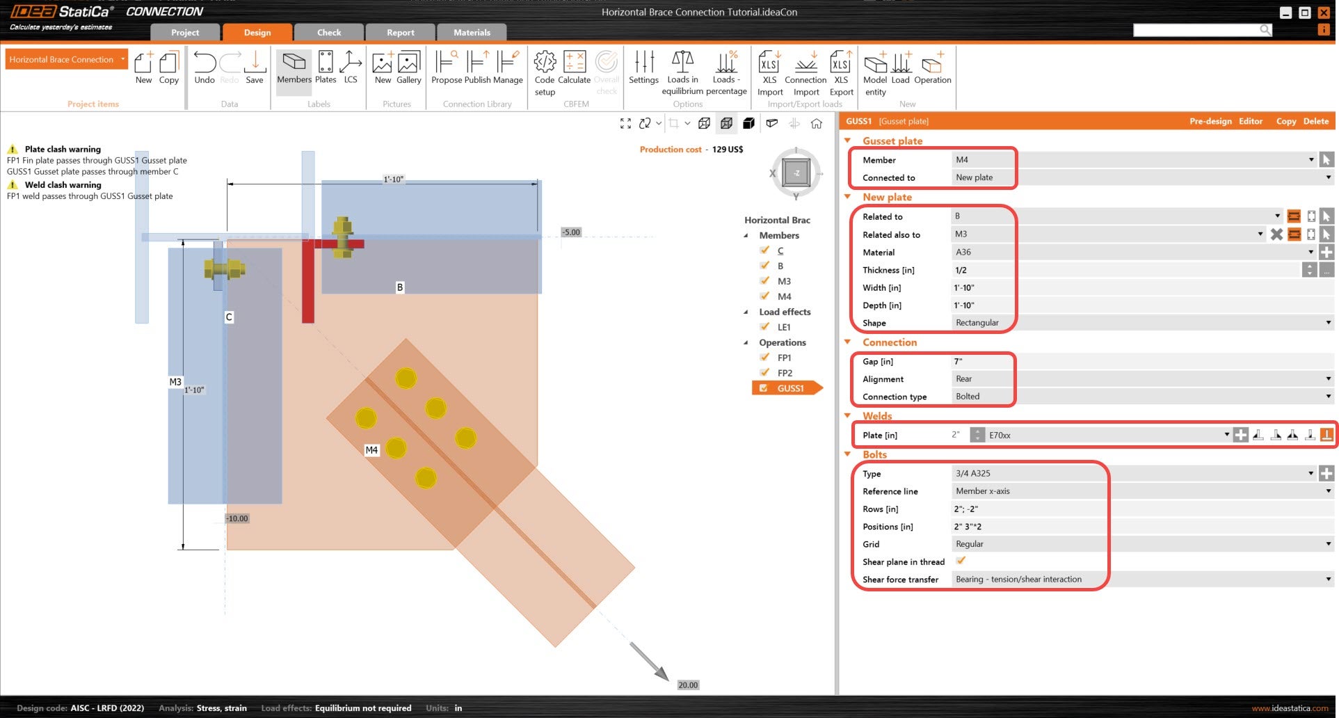
Now, add the Gusset plate operation.
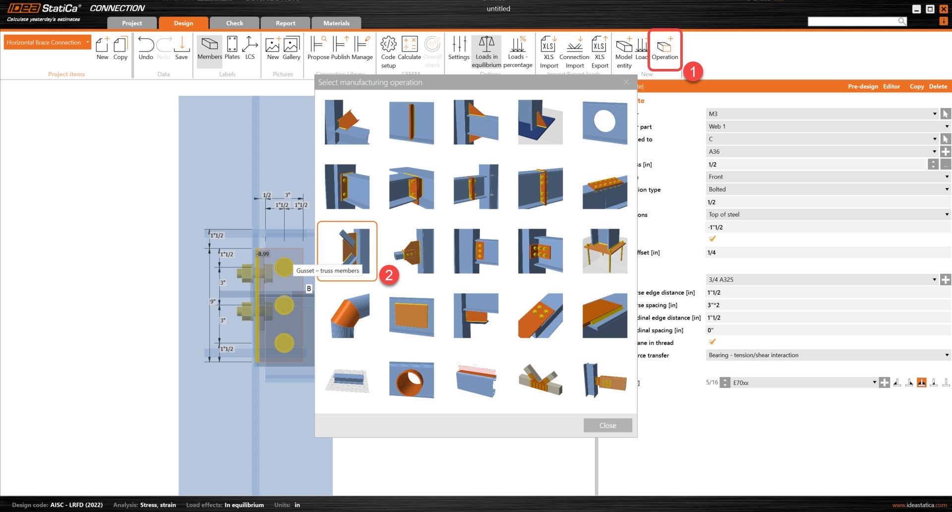
And redefine its properties.
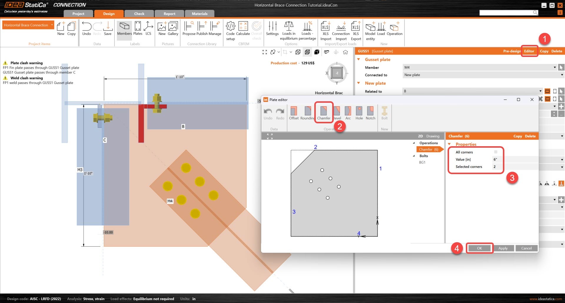
Let's start to edit the gusset plate. First, under editor, the corner at the end of the bolts will be removed.
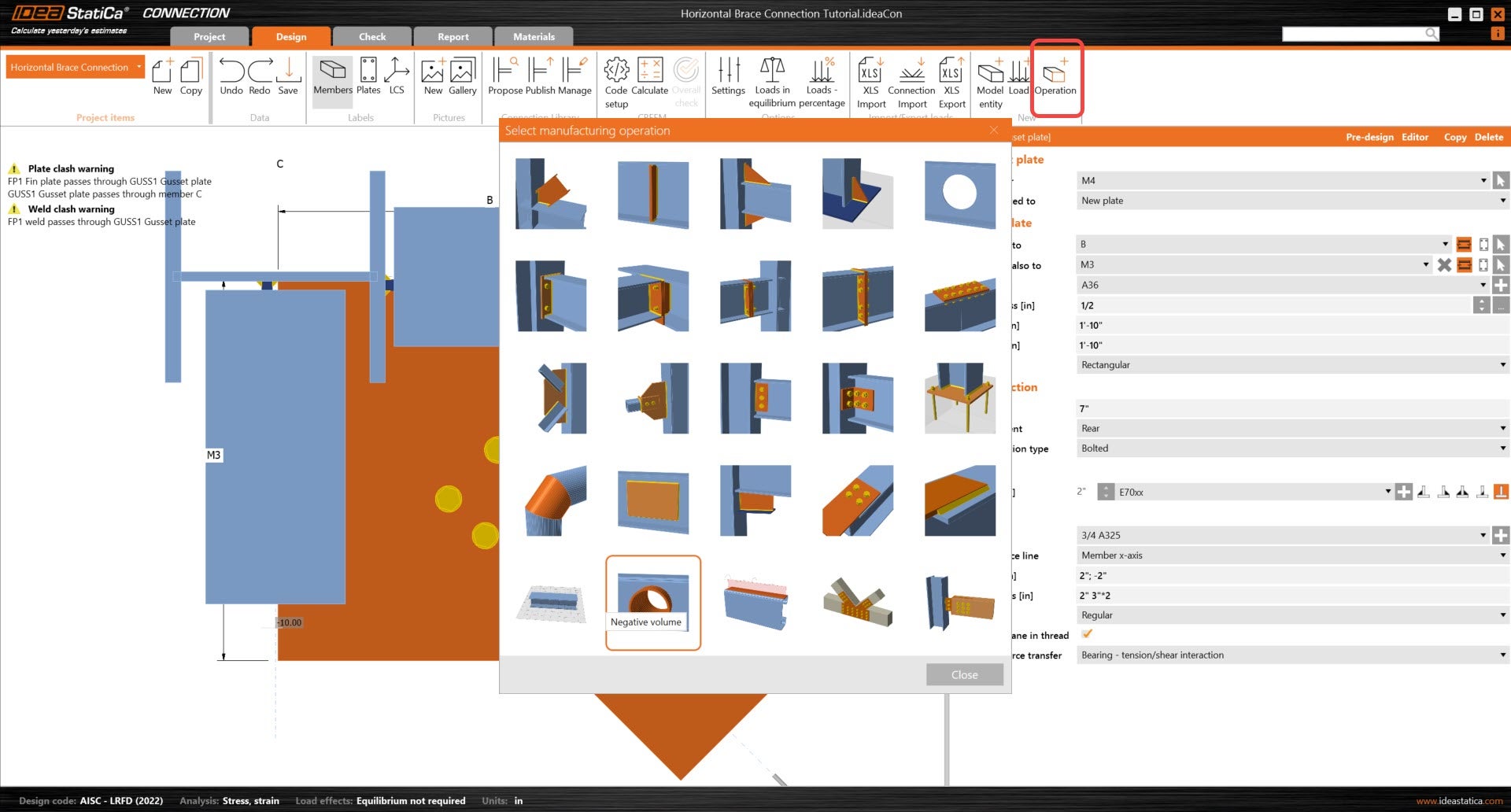
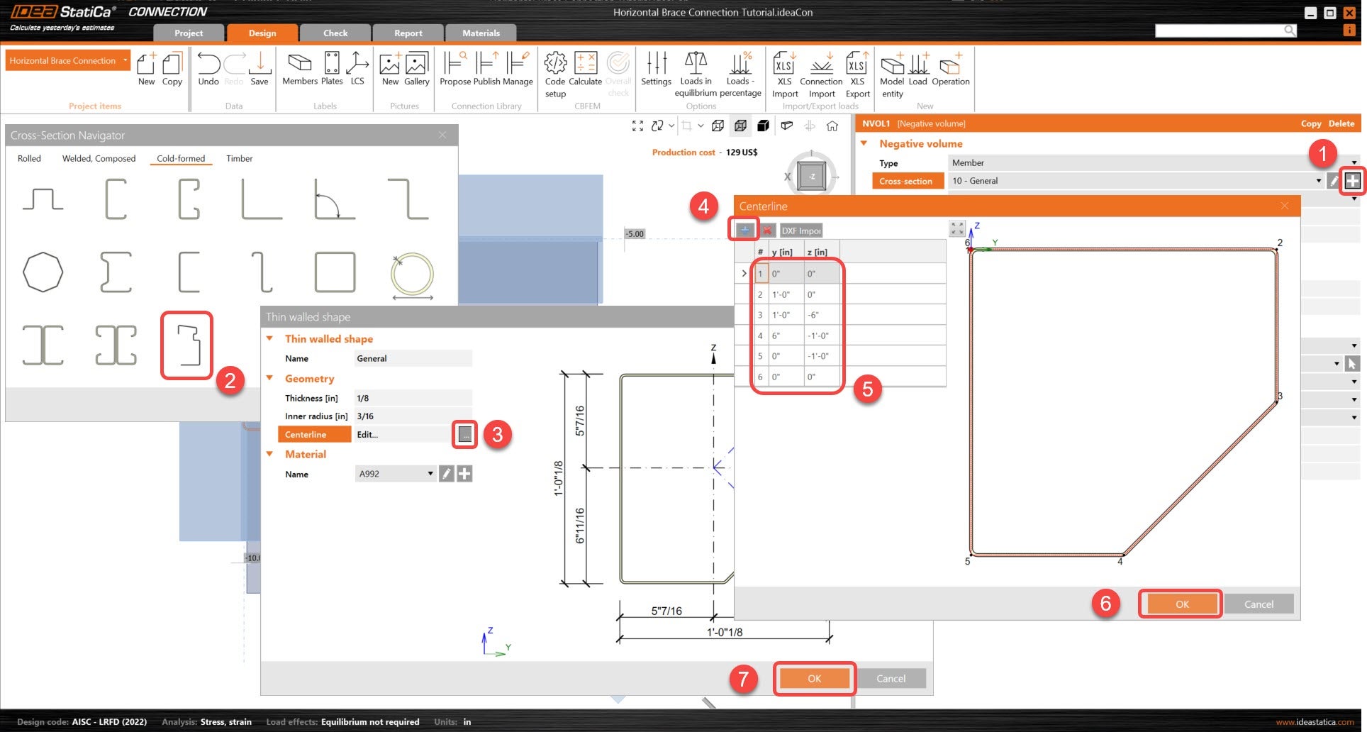
Next, a more complex cut will be created on the gusset plate using a combination of operations. Start with the Negative volume operation so that the complex opening can be created.
Update the negative volume cross-section. Using the CF general shape option, a cross-section can be created based on either a .dxf file or through point coordinates. In this tutorial, point coordinates will be used.
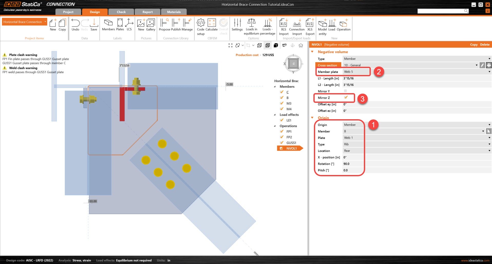
Adjust the location of the negative volume. Using a member as the origin instead of node allows the user to use members as references rather than having to input coordinates manually.
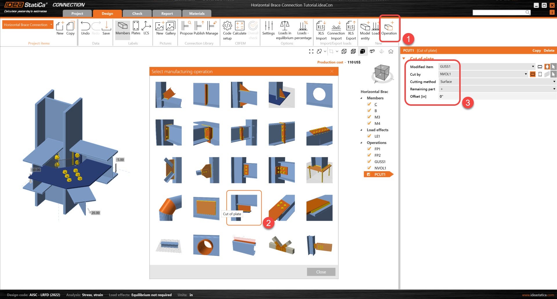
Next using a Cut of plate operation, the user will be able to cut the gusset plate by the negative volume. This will allow us to have a finalized shape for the gusset plate.
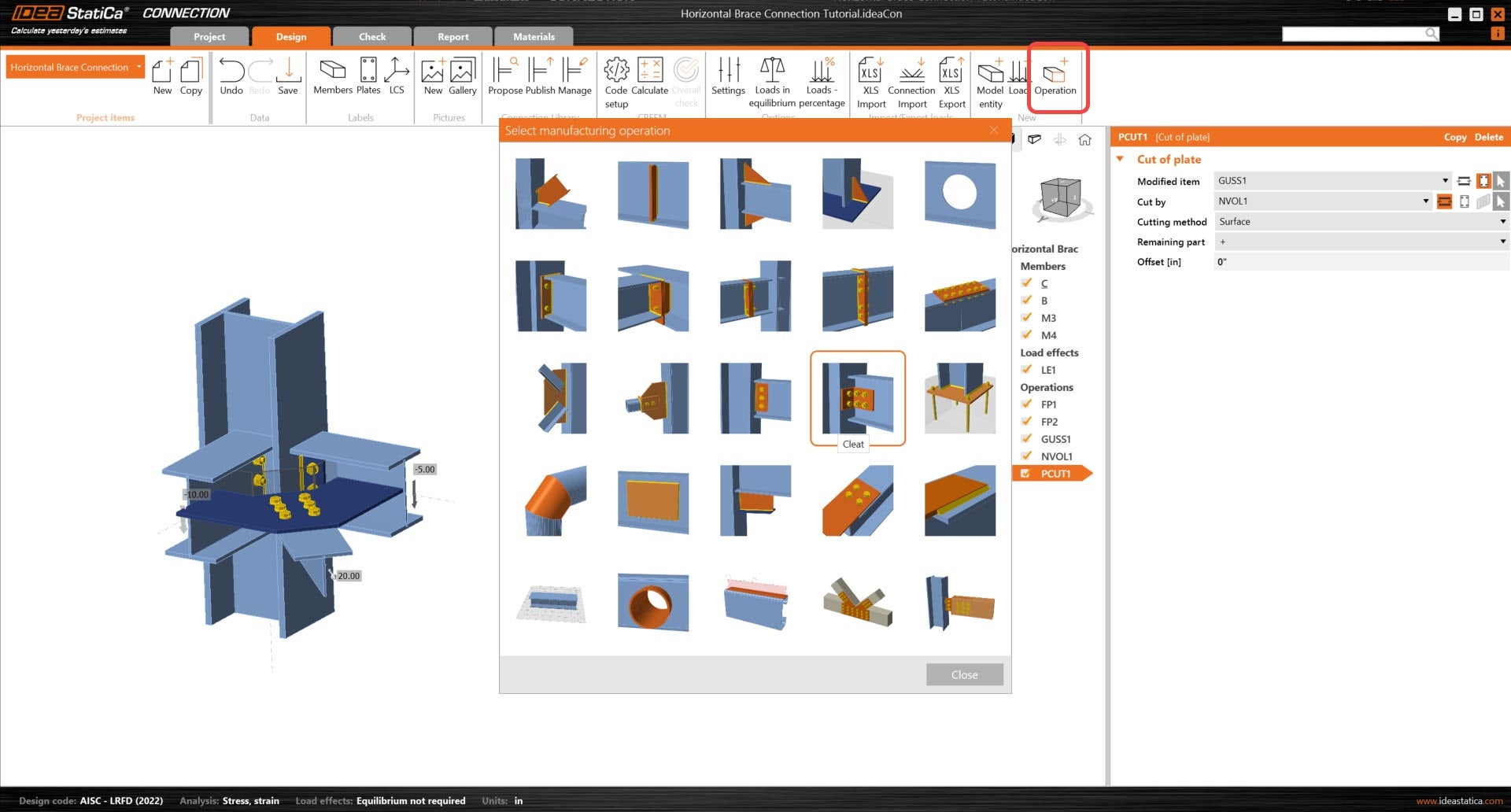
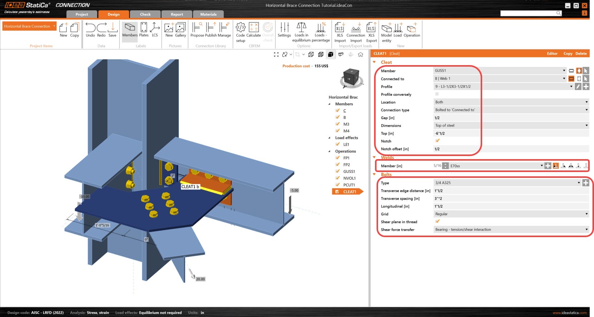
The Gusset plate will now be connected to the beams. Add a new Cleat operation and adjust its parameters so that it is connected to member B.
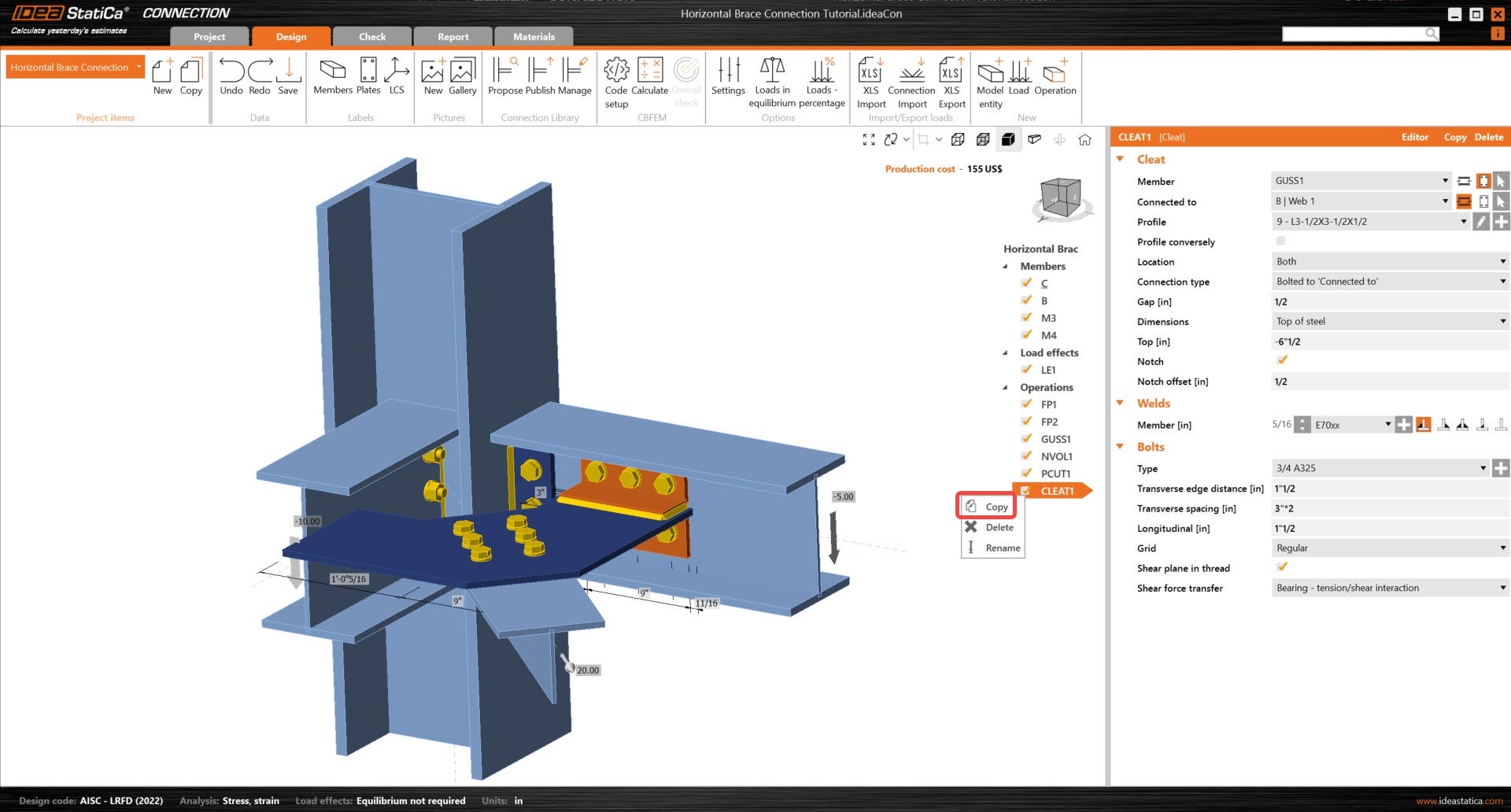
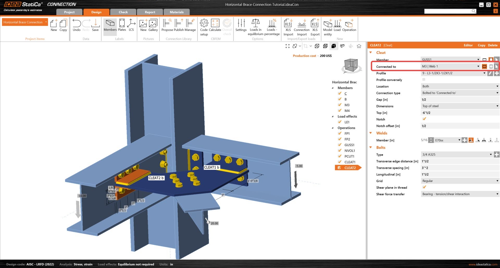
Next, copy the cleat operation and adjust the parameters so that the new cleat operation is connecting the gusset plate and member M3.
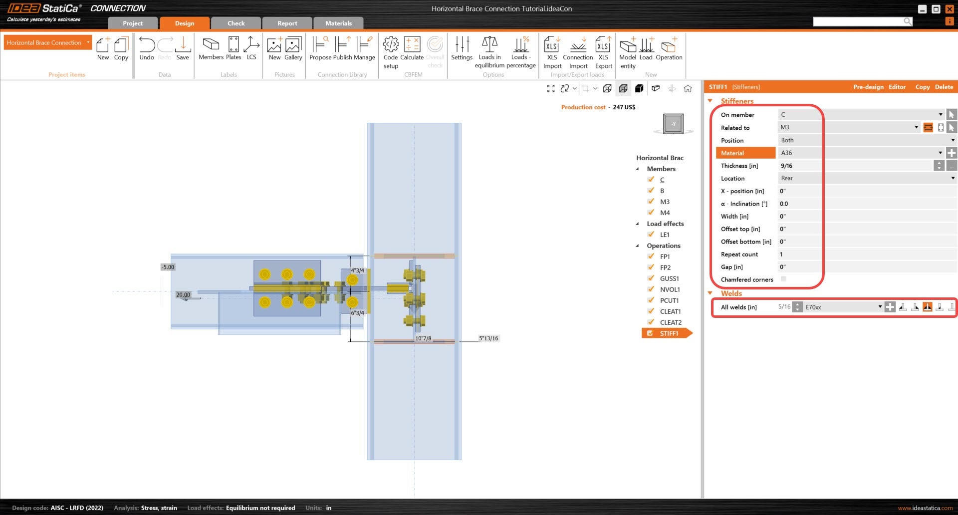
Finish the design with the operation Stiffener.
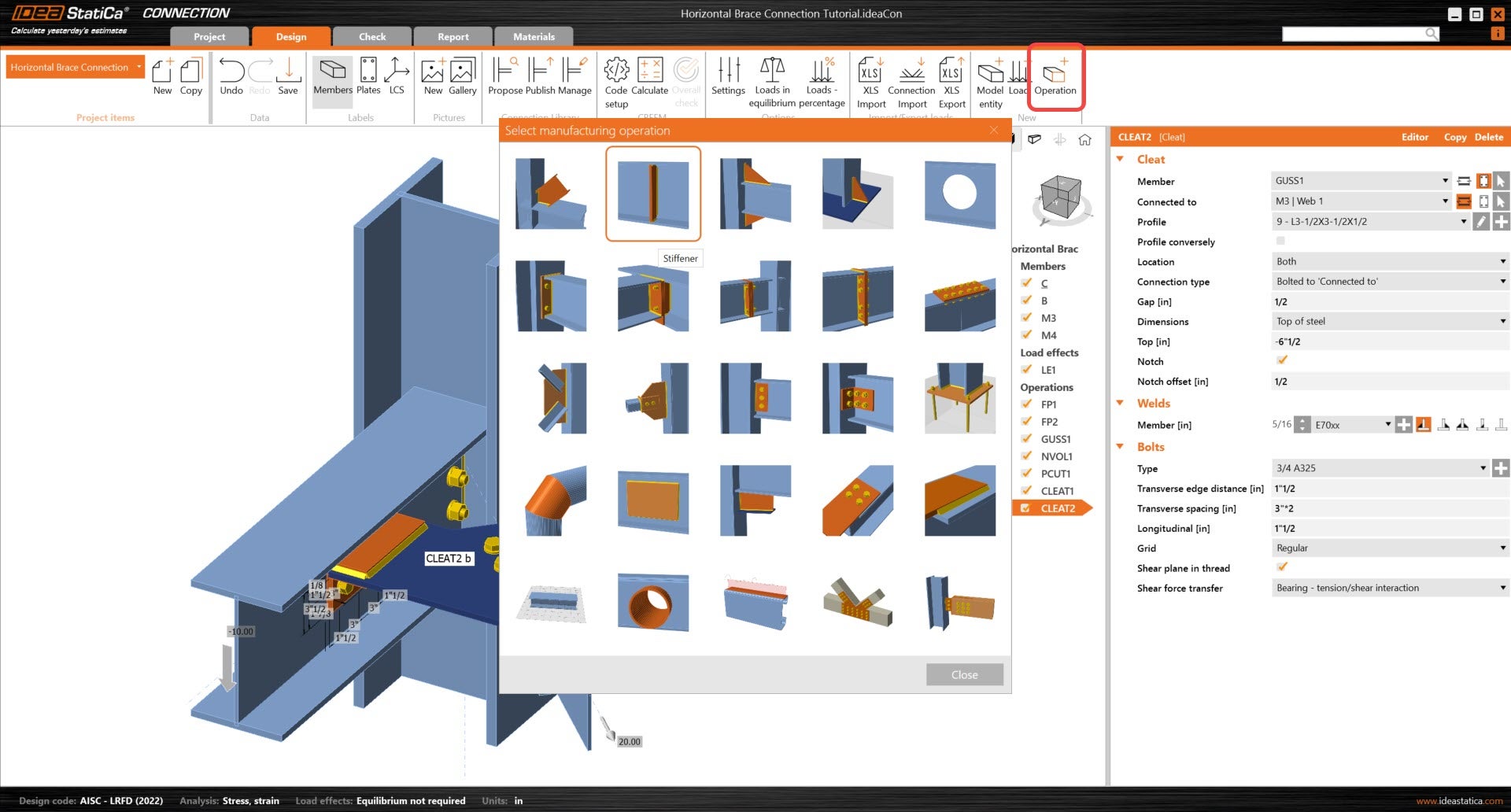
And set the correct properties of STIFF1.
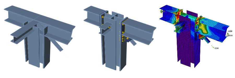
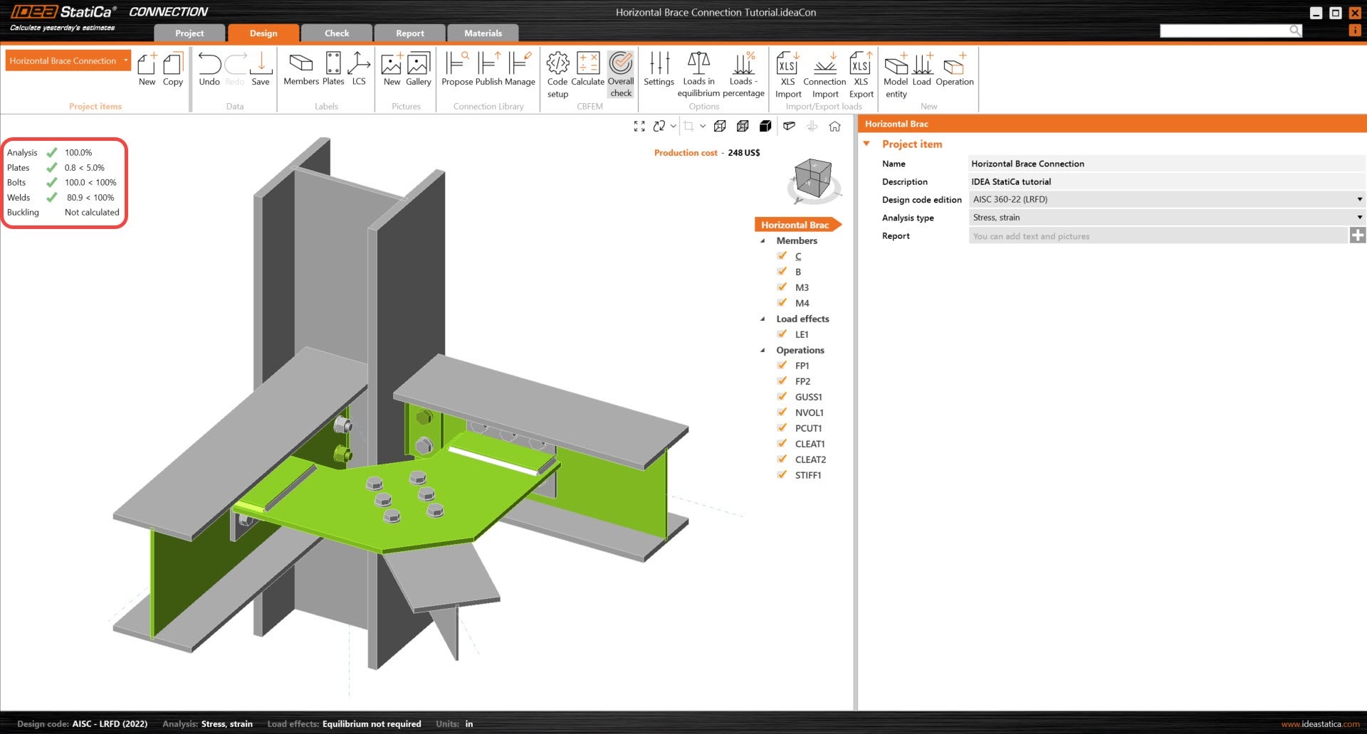
Let’s check the final design of the joint.
5 Calculation and Check
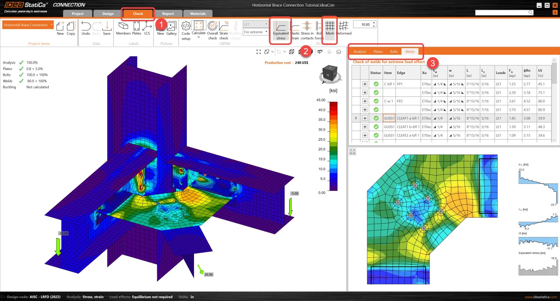
Start the analysis by clicking Calculate in the ribbon. The analysis model is automatically generated, the calculation based on CBFEM is performed, and the Overall check is displayed together with the fundamental values of check results.
Go to the display tab Check, and activate Equivalent stress and Mesh from the ribbon to get a complete picture of what is happening in the joint. Go through the different results for all components (Plates, bolts & welds).
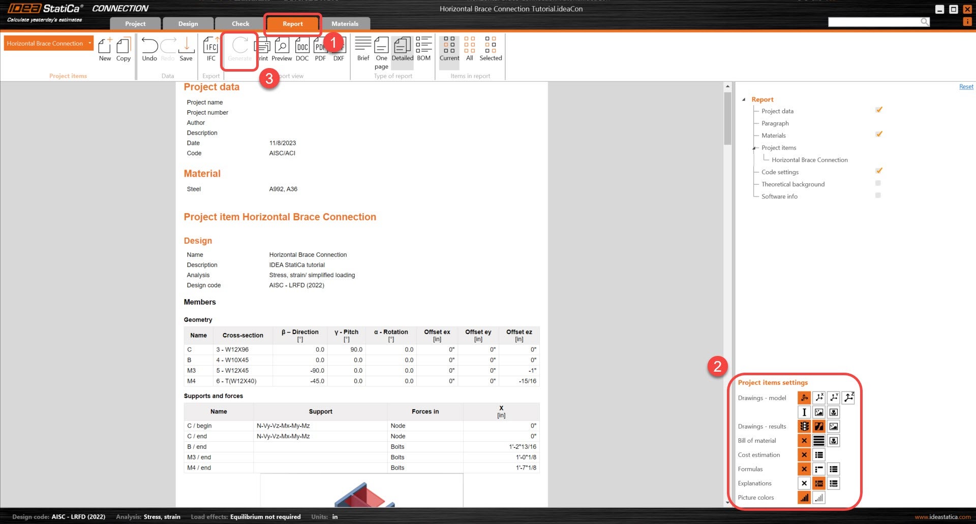
6 Report
At last, go to the tab Report. IDEA StatiCa offers a fully customizable report where you can add or remove as much detail as needed. Once done, click Generate and the report will be generated with the parameters it was given.
You have designed, optimized, and code-checked a structural steel joint according to AISC.
Learn how to use IDEA StatiCa effectively with our self-paced e-learning courses
Start learning