


1 - What do the deformations tell you?
The first thing I do after running a Connection model is open the deformation results. They provide insight into how the connection behaves and how forces are transferred through the model. Combined with the mesh, the equivalent stress plot and, where relevant, the bolt forces, this provides a quick visual check of your steel connection design.
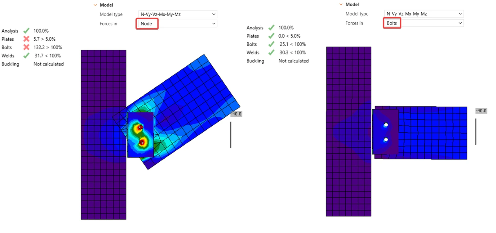
Figure 1: Unexpected deformation due to incorrect modelling
Figure 1 shows an example of a connection that has not been modelled correctly. The incorrect definition of forces in a shear connection results in an unrealistic upward deformation of the member. For a detailed explanation of this modelling issue and how to avoid it, see the related article: How to define correct load position (Forces in).
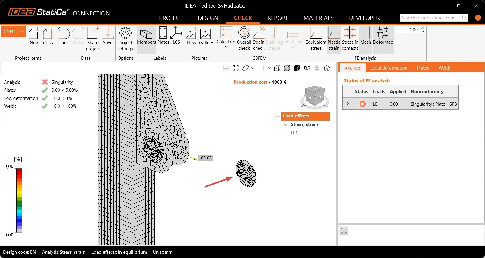
Figure 2: Singularity caused by an unconnected part
The deformed shape also helps you identify calculation errors. In Figure 2, the analysis stops due to a singularity. Looking at the deformed state, we can see a plate separating from the rest of the model because it is not properly connected. Reviewing the deformation results immediately points you to the source of the problem.
2 - Have you checked the unbalanced forces?
In general, I always recommend balancing the forces in the node. That's also why I don't recommend deactivating the Loads in equilibrium option. Defining the forces for all members encourages you to think about all the loads in the connection design.
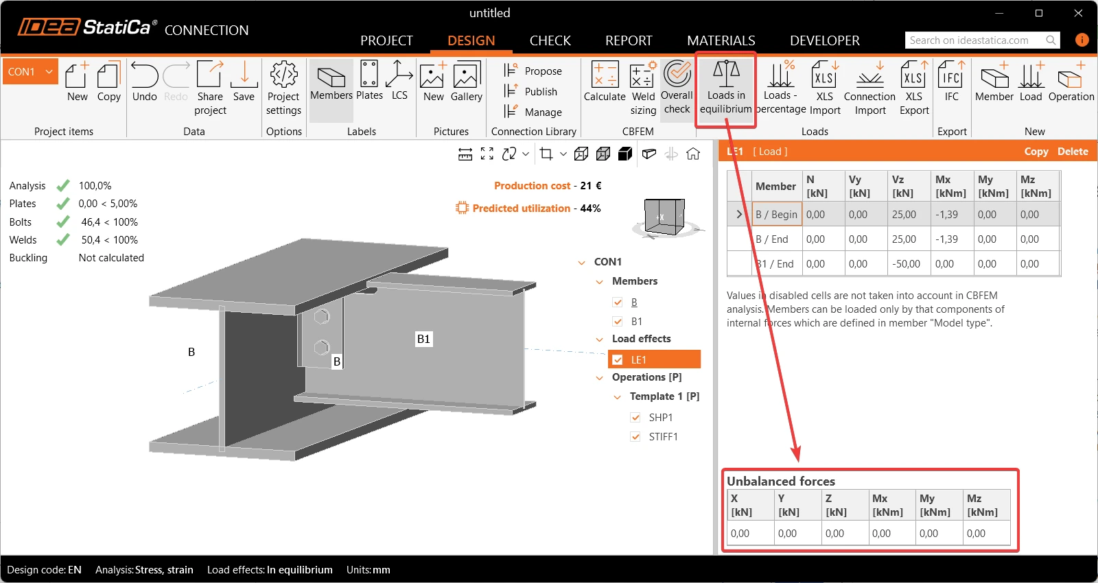
Figure 3: Table of Unbalanced forces
In some situations, I do come across unbalanced forces, for example due to eccentricities in the connection. When this happens, I always check where these forces should be transferred and manually apply them to the relevant members.
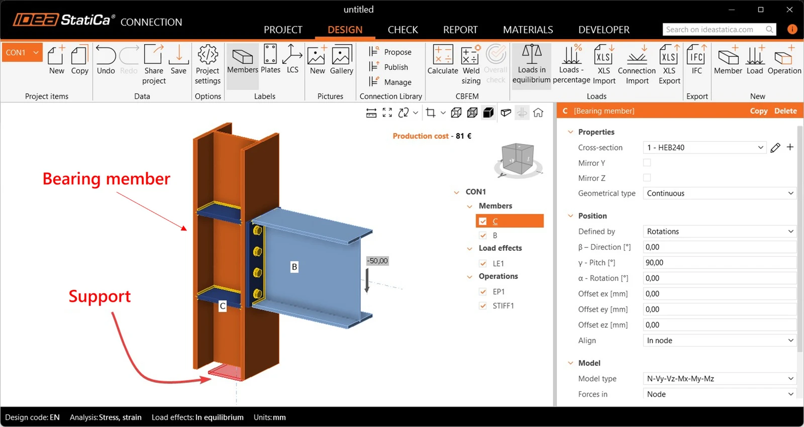
Figure 4: Bearing member and support
If you ignore the unbalanced forces, they don't just disappear. They are transferred to the bearing member and eventually reach the support, as indicated by the red rectangle in Figure 4. Consequently, this load path may not accurately represent the actual behavior of the structure.
3 - The Model type affects more than just the forces you can enter
At first glance, the Model type setting seems to only determine which internal forces can be entered for a member. In reality, it introduces additional boundary conditions that change the CBFEM computational model. That's why it's important to understand the underlying principle before changing the Model type.
For a single-bolted connection, we normally change the Model type to N-Vy-Vz. Otherwise, the member can freely rotate around the bolt, and causing the calculation to fail. In other situations, I would be cautious about changing the Model type, as it creates a statically indeterminate system where residual reactions may occur.
Figure 5 shows an example where I applied the N-Vy-Vz model type to member B to demonstrate the resulting behavior.
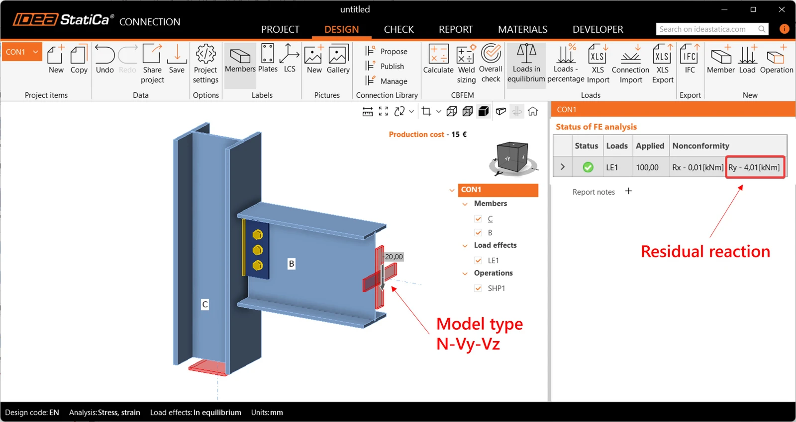
Figure 5: Residual reaction Ry
In this example, the rotation around the local y-axis is restrained for member B. This results in a reaction moment of Ry = 4 kNm, as shown in the nonconformity table. This value is equal to the bending moment caused by the eccentricity of the shear force at the bolt row. For this example, it is better to use the default Model type and set the "Forces In" option to "Bolts".
The effect of the Model type setting should always be considered carefully. It is the right tool for solving issues such as a single-bolt singularity or a twisting U-section, but always check the residual reactions in the analysis table afterwards.
4 - Cutting over shifting
A common modelling choice I see is using Offset ex to adjust member positions. While this works in some cases, I have learned that it is better to avoid this approach. By applying an Offset ex, we unintentionally change the location where the forces are applied, introducing an eccentricity.
Consider the situation below (Figure 6): we need to extend the column to align with the top flange of the beam. We could achieve this using Offset ex, but this would result in an incorrect point of force application. A better approach is to cut the member and activate the option "Extend the member" in the Cut operation.
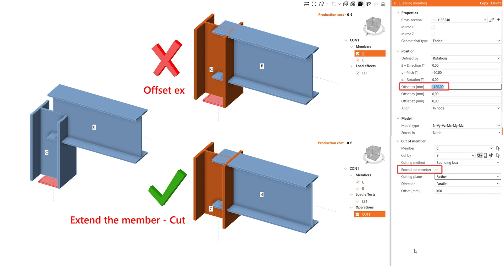
Figure 6: Extending the member using the Cut operation instead of Offset ex
Another example where cutting is preferred over shifting is when welding a plate to another element. I prefer to make the plate slightly larger and then apply cut operations. The plate is cut, and the welds are generated automatically.
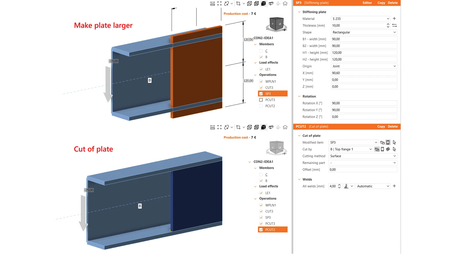
Figure 7: Make the plate larger, then cut
The additional advantage is that when you later change the profile or other dimensions slightly, the welds are still correctly defined, and you don't have to shift the plate again and again.
5 - Back to the basic operations
Sometimes, a combined operation in IDEA StatiCa does not give you the flexibility you need. In those situations, I go back to the basic operations: stiffening plate, cut of member, cut of plate, weld or contact element, and fastener grid.
With these basic operations, you can model almost anything. The downside is that it requires more individual operations and therefore more clicks, but it gives you much more control over the final result.
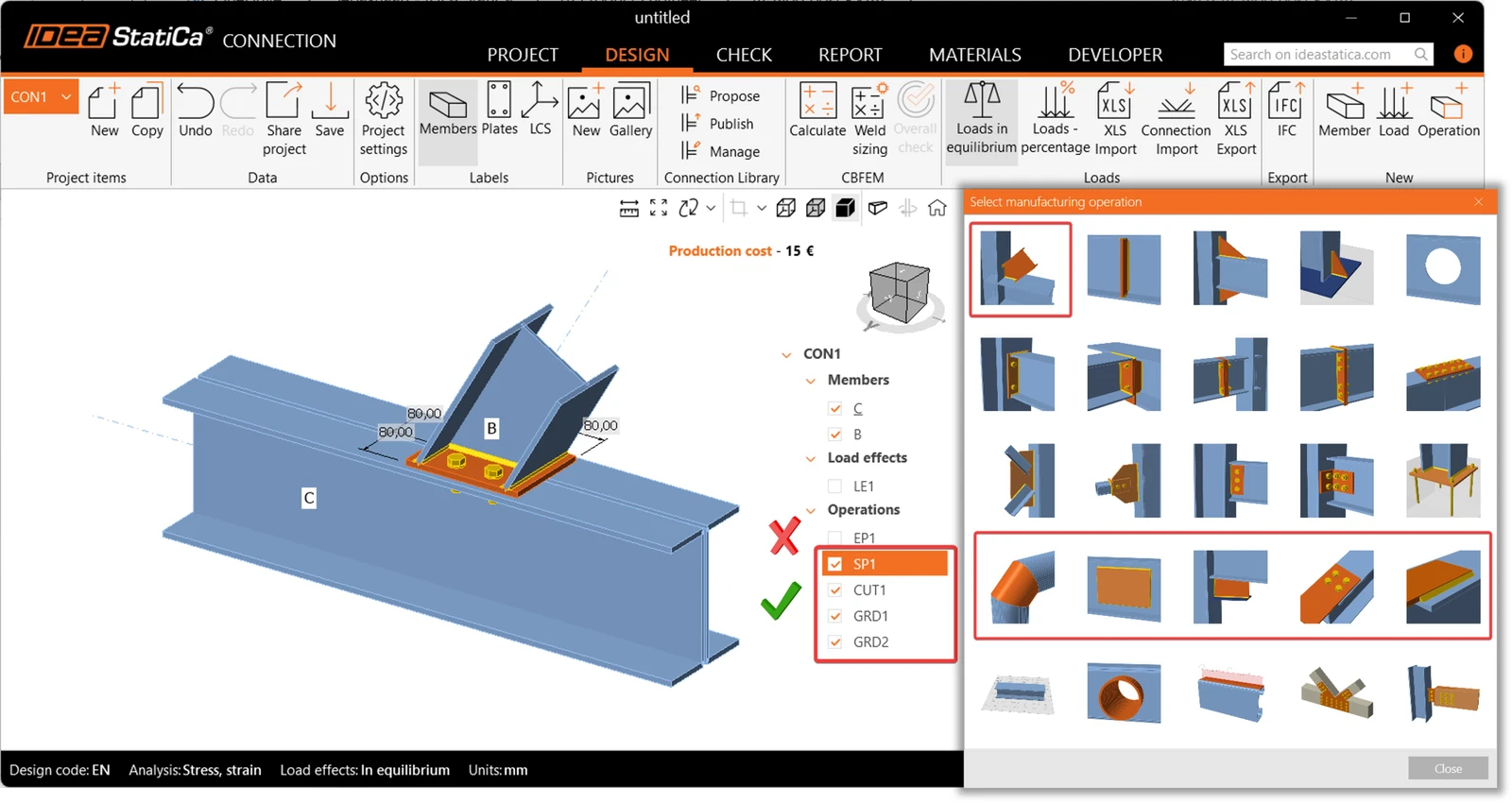
Figure 8: Basic operations give more flexibility
Figure 8 shows a good example where an endplate is applied to a member consisting of two sections (2xUNP). The endplate operation cannot be applied directly to both flanges in the required manner. Instead, I created the connection manually:
- Model the endplate as a separate stiffening plate.
- Cut the member using the plate.
- Apply the bolts using two separate fastener grid operations.
It takes more operations, but I have full control over the final model.
Conclusion
Good connection modelling in IDEA StatiCa is not about knowing every advanced feature. It is about understanding how the software interprets your input and how that affects the behavior of your model. Always check the deformations first, keep your forces in equilibrium, understand what the Model type adds to the CBFEM model, use cuts instead of unnecessary offsets, and know the limitations of your operations.
Working with IDEA StatiCa Connection has been a great learning experience for me. The modelling approach is different from traditional structural software, but once you understand the principles behind it, it becomes a very powerful tool. More importantly, it has helped me develop a deeper understanding of steel connection design.
While working with IDEA StatiCa Connection, I have learned a lot about topics such as eccentricities, plastic strains, and Eurocode requirements that I had not previously encountered in detail. For me, that is one of the biggest strengths of the software: it does not only help you design connections, it also helps you understand the engineering behind them.
Try IDEA StatiCa for free
Start your trial today and enjoy 14 days of full access and services free of charge.
Start free trial