

How to activate the link
- Download and install the latest version of IDEA StatiCa
- Make sure that you are using a supported version of your FEA solution
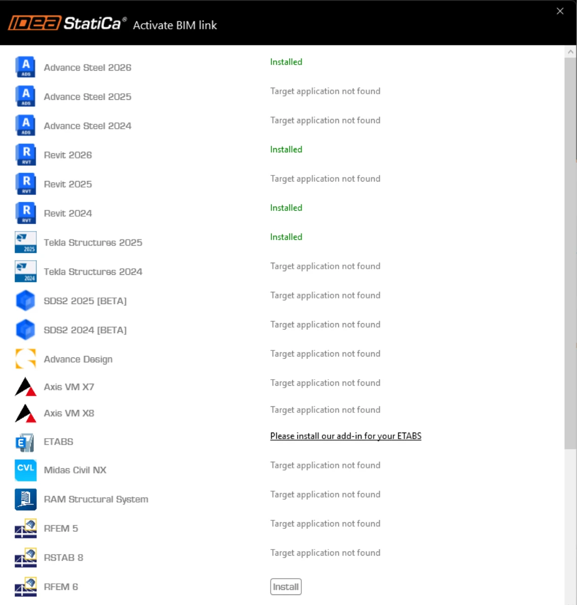
IDEA StatiCa integrates BIM links into your FEA software during its installation. You can check the status and eventually integrate more BIM links by running IDEA StatiCa and opening the BIM links. Please note that some FEA software require additional steps to fully activate their BIM link to IDEA StatiCa.
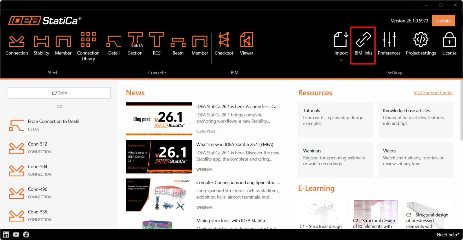
A notification "Do you want to allow this app to make changes to your device?" may appear, if so, please confirm with the Yes button.
By clicking Install, the BIM link for the selected software is integrated. The screen also tells you the status of other BIM links.
How to use the link
Download the attached project, open it in SCIA Engineer, and run the linear analysis to get the internal forces over the structure.
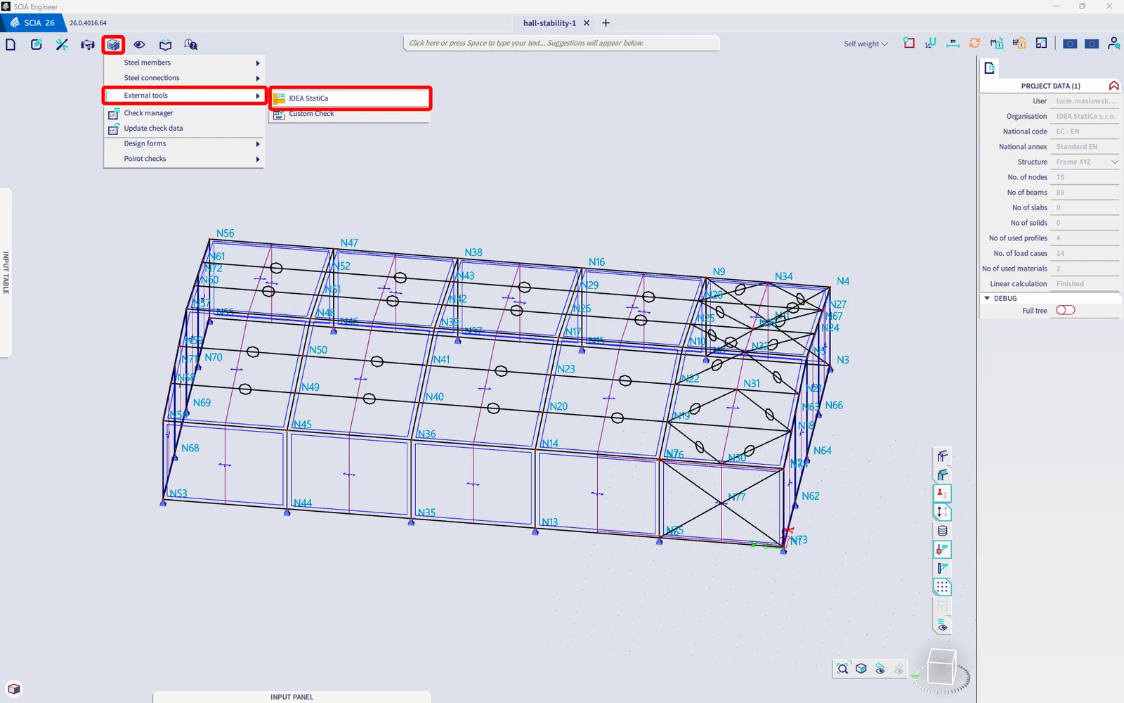
The BIM link is automatically integrated. You can find it in the top ribbon under Design -> External tools -> IDEA StatiCa.
Or run the "IDEA StatiCa" command in the top command line.
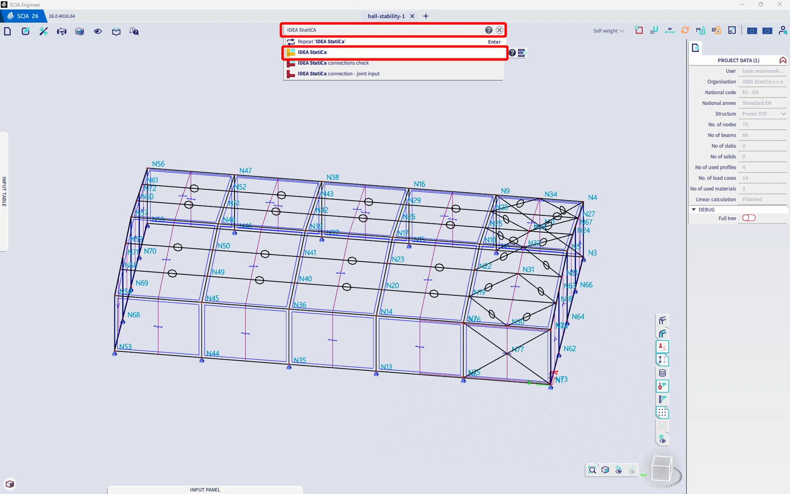
Both of these options will open the Checkbot application.
Select the Checkbot workflow and design code EN. Then select Create project.
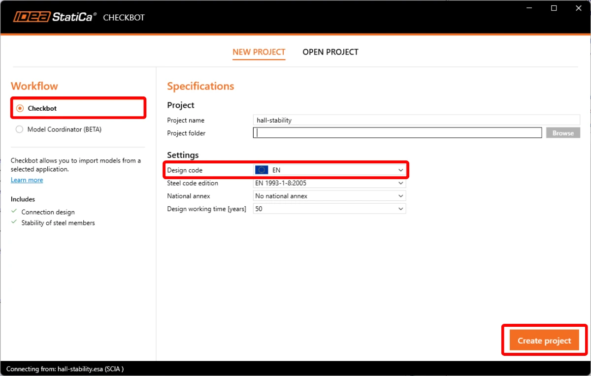
The new Checkbot project is ready to import the structure from SCIA Engineer.
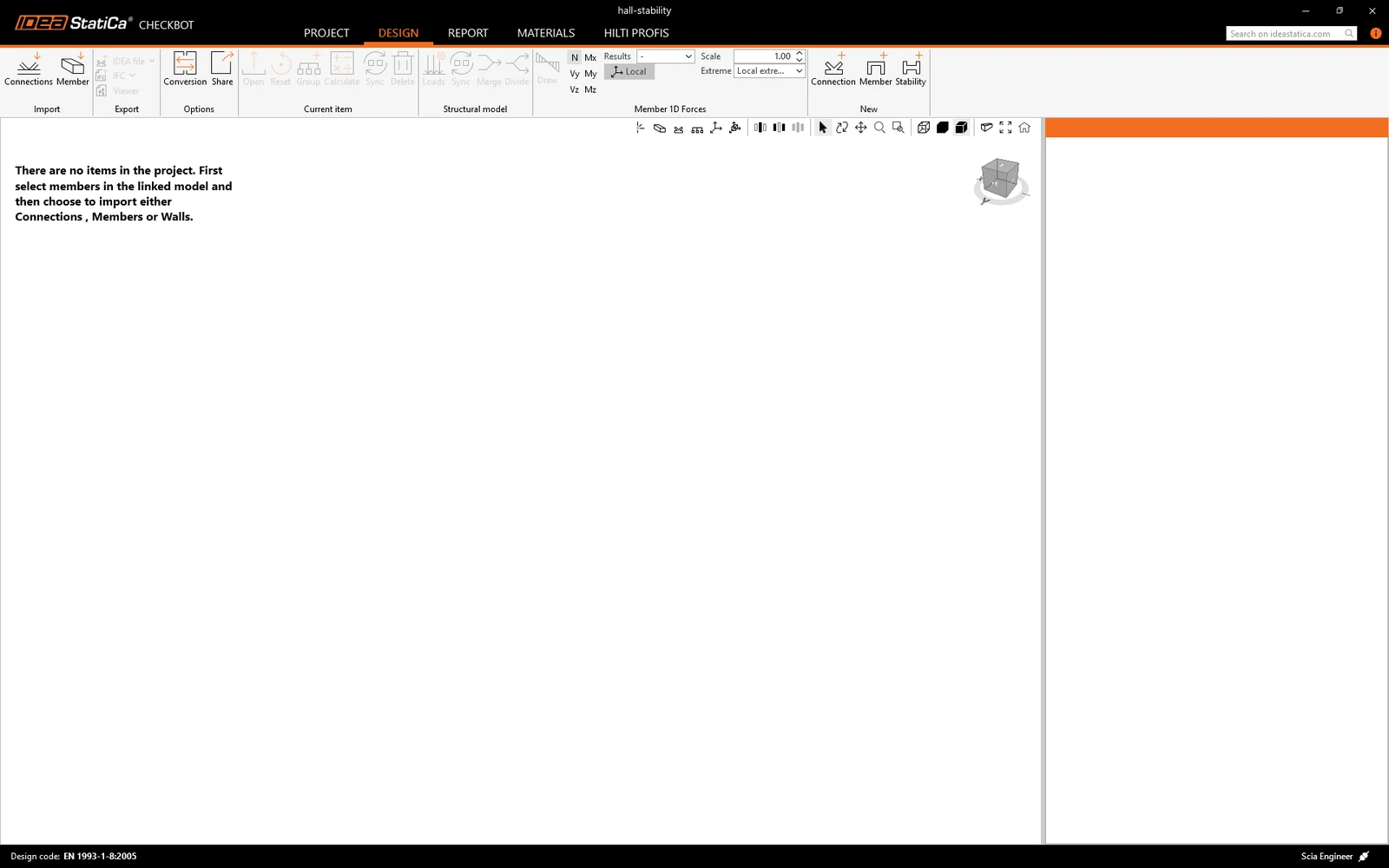
Now switch back to the SCIA Engineer window and select the whole structure.
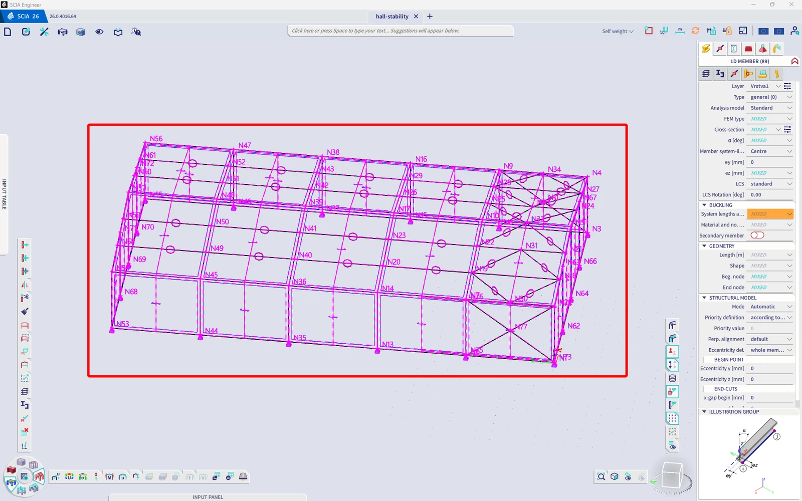
Import
Then in Checkbot select Member.
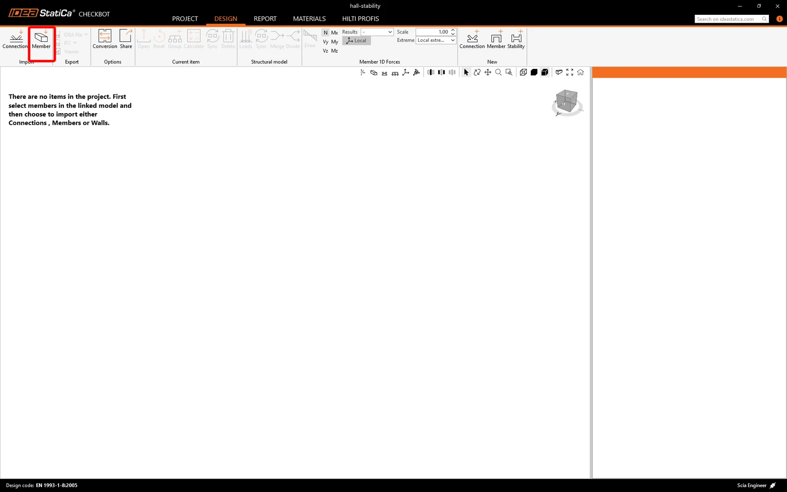
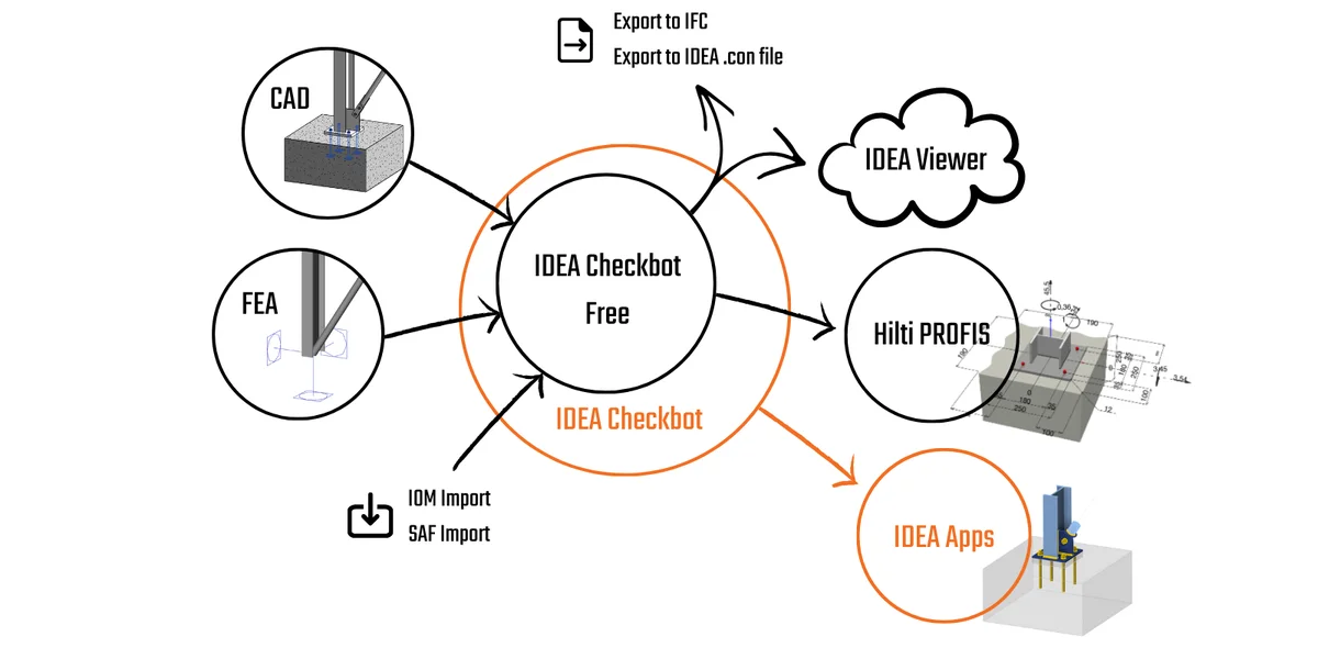
This will import the selected structure and its load effects into Checkbot - with the same coordinates, orientations, and section sizes as per the FEA model.
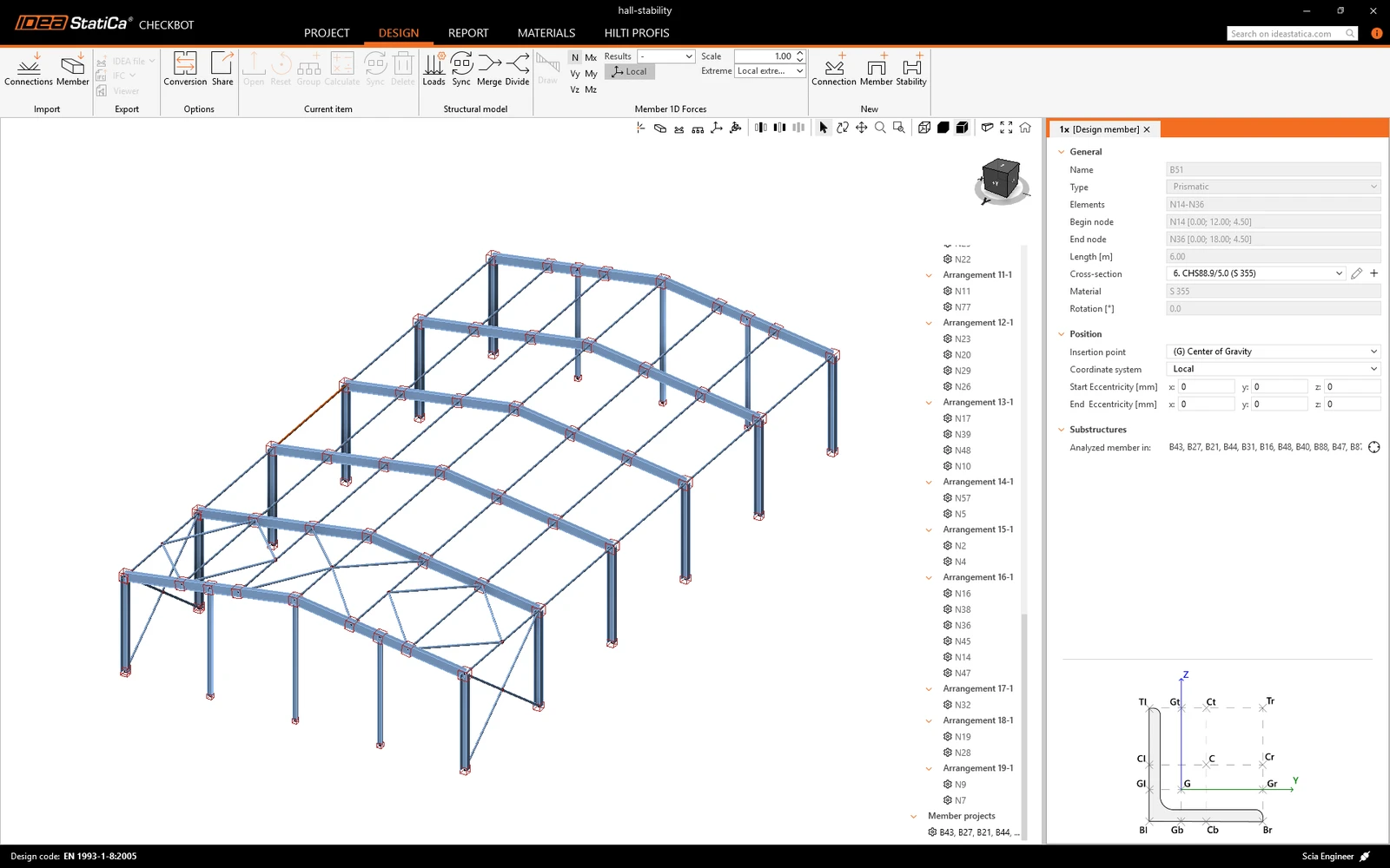
Please note that the 3D workspace is designed to show an overview of the imported structure and not a detailed view of the actual connections. For more information on Checkbot, see here.
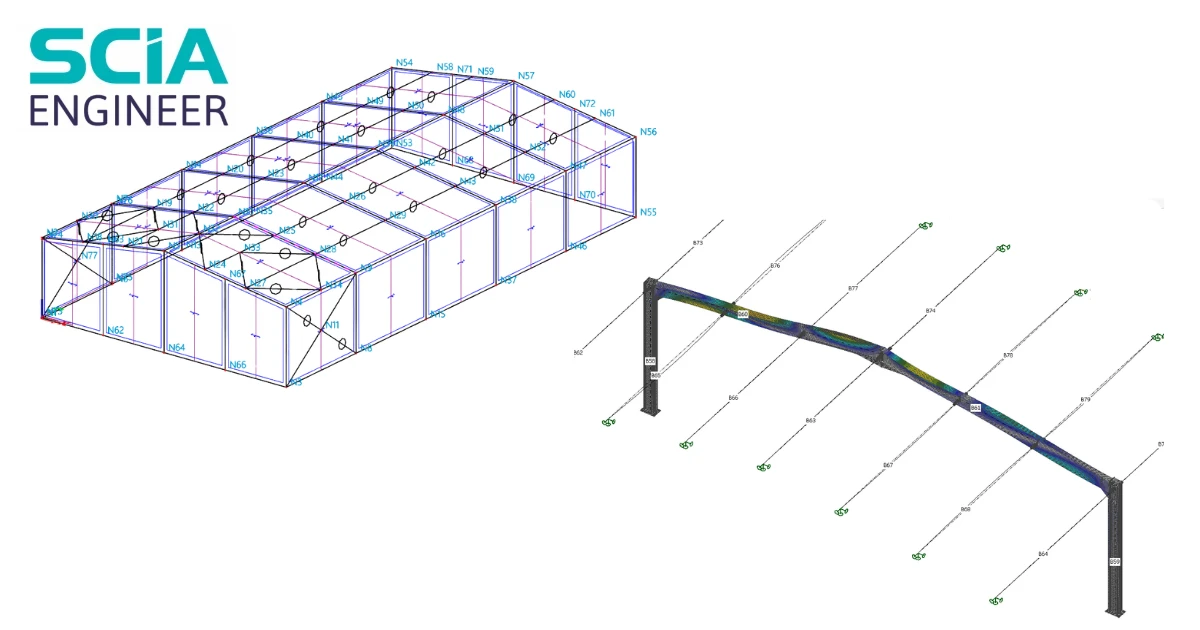
In this tutorial, we will check the stability of a steel hall frame.
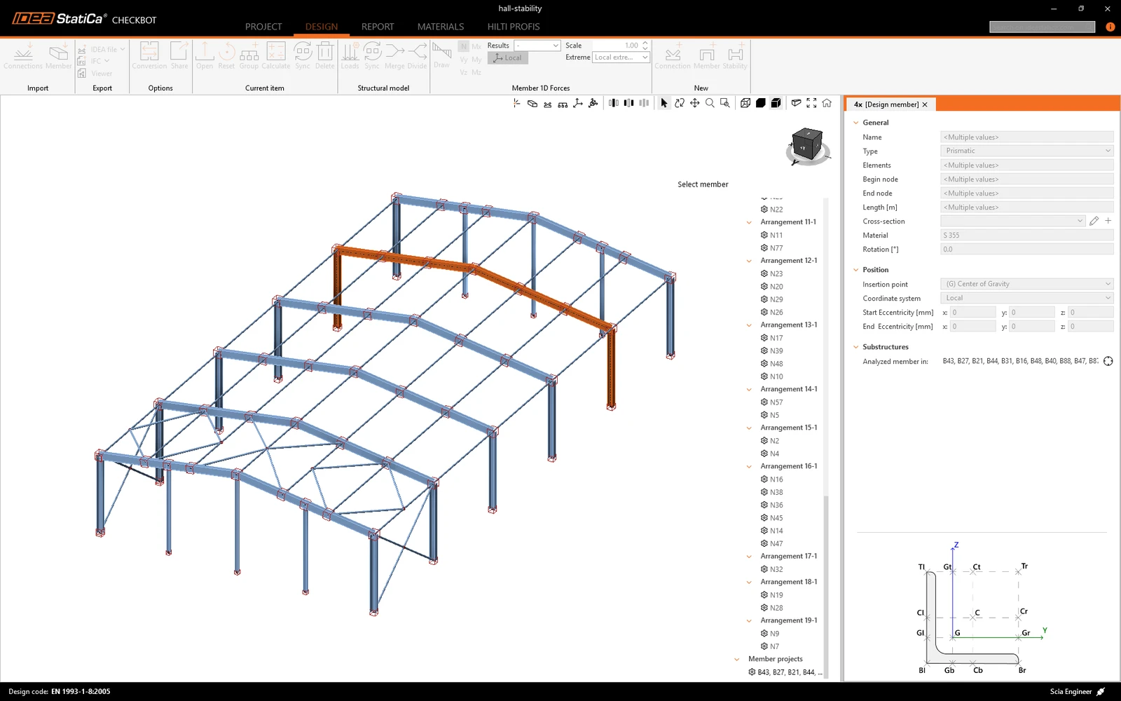
Connection design
Before the stability check in IDEA StatiCa Stability, we first need to design the connections of the frame and the connected members in IDEA StatiCa Connection, so that the real stiffness of the joints can be taken into account in the analysis.
To make the design more efficient, create groups of identical connections. This way, you only need to design the reference connection, and the same design is automatically applied to the rest of the group.
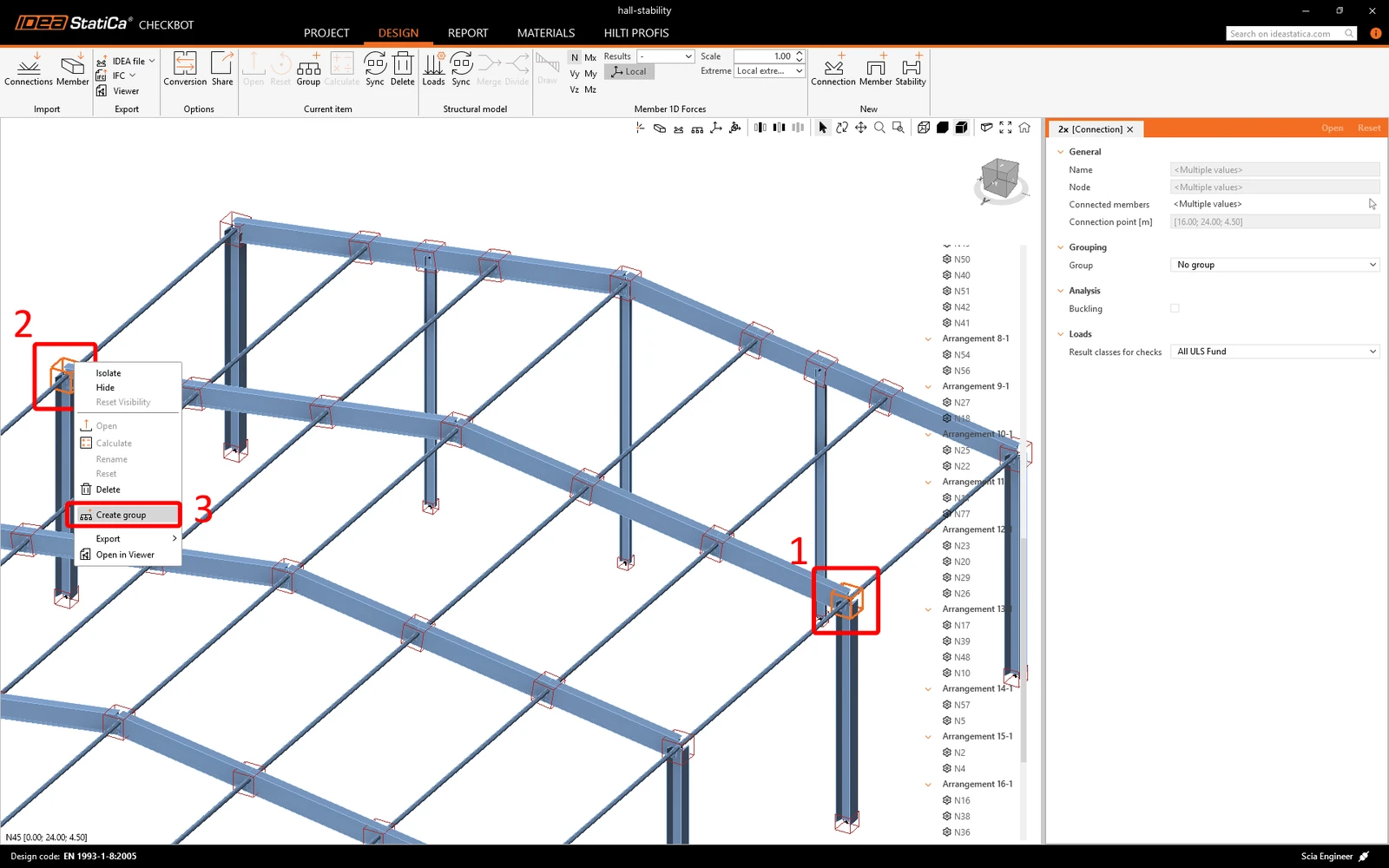
Select the connections with the same geometry, right-click, and create a new group. Repeat this for the remaining connection groups.
Once the groups are created, Open the reference connection (underlined in the tree menu).
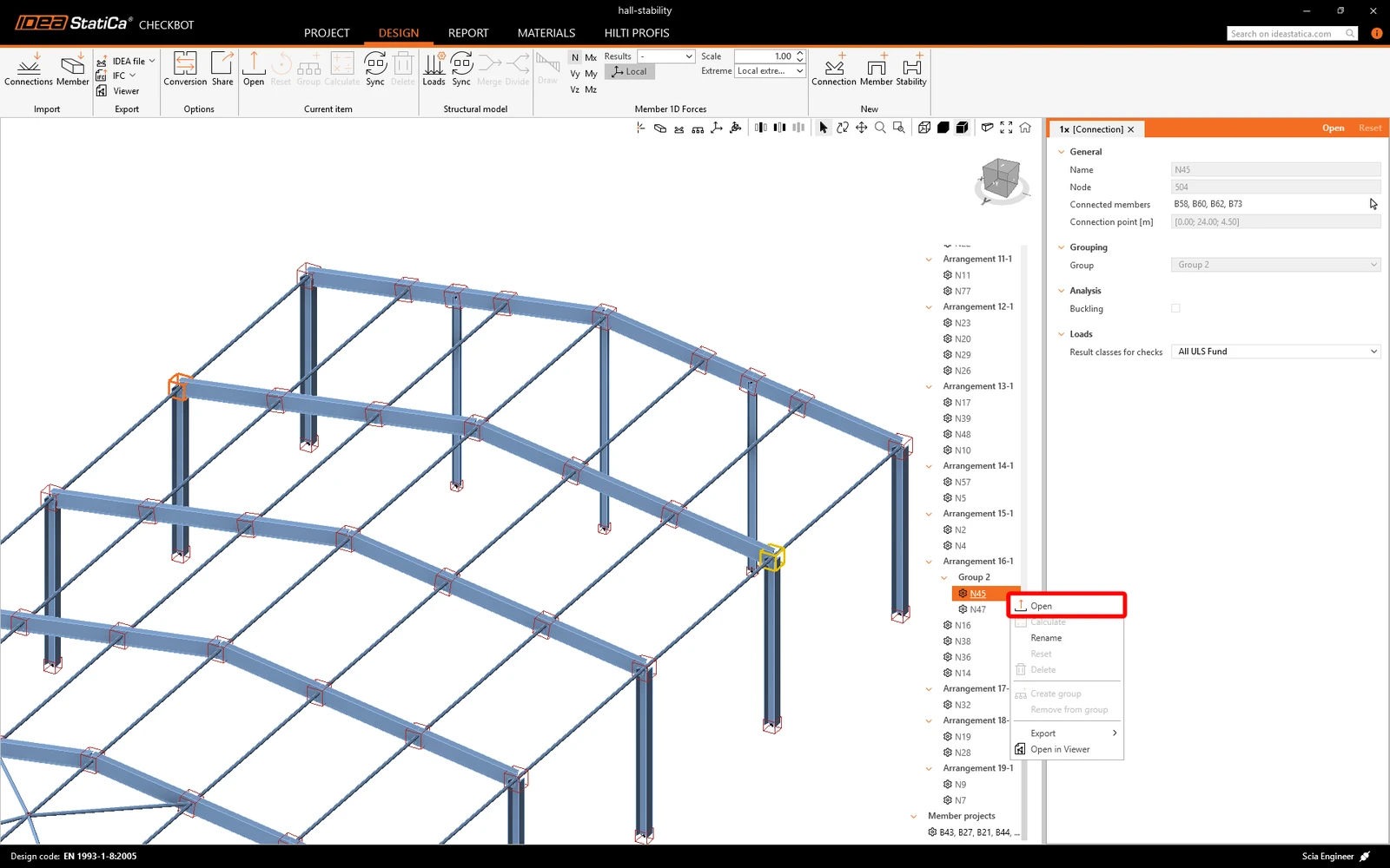
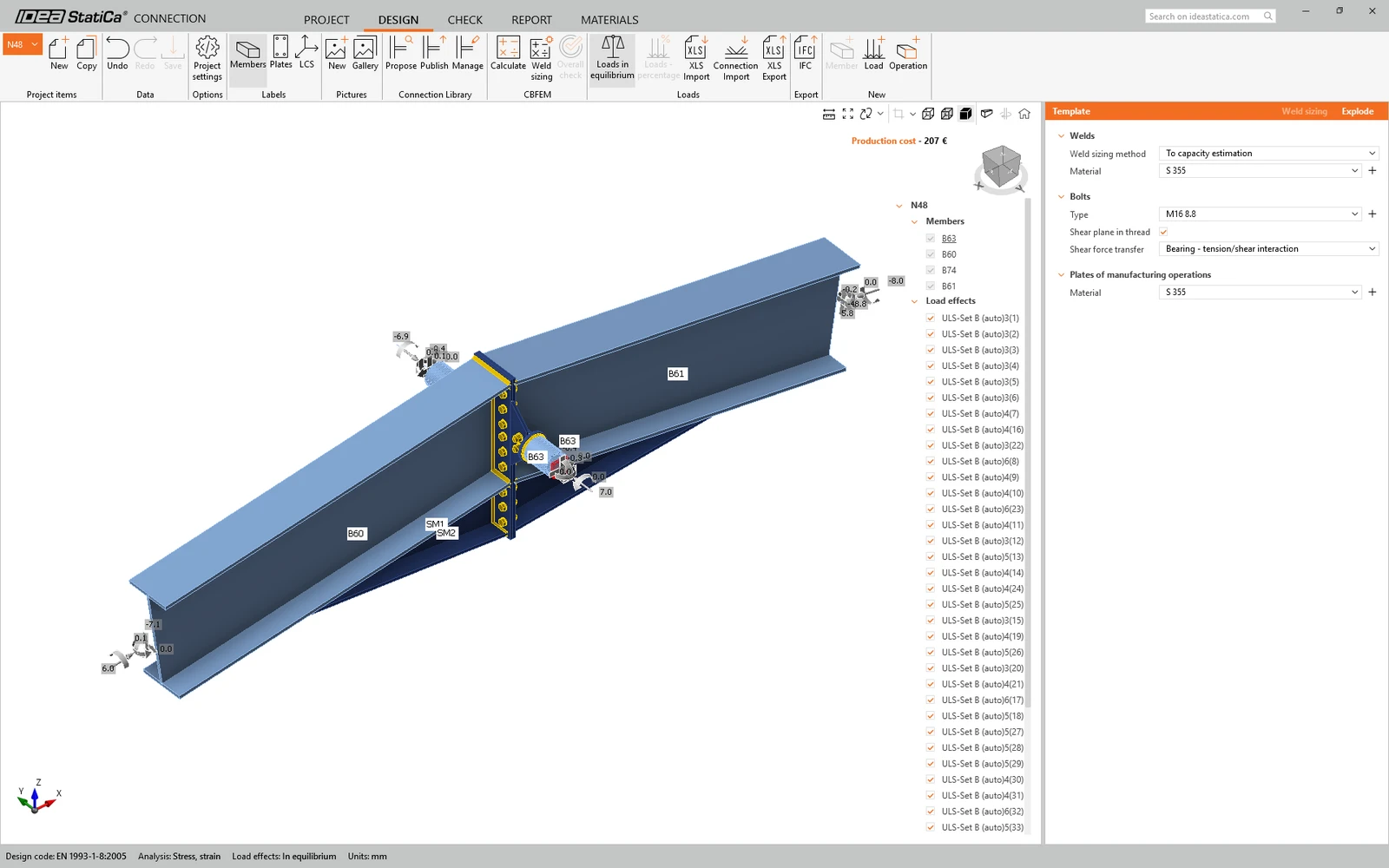
The connection is opened in the IDEA StatiCa Connection.
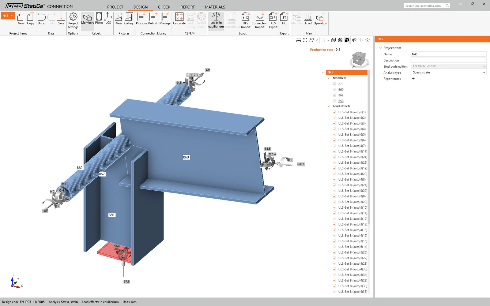
Now design the connections.
You can use the prepared designs, which you will find in the project folder you downloaded earlier. Open the connection file, Publish the connection to the Connection Library, and then use Propose to apply it to the connection in your project.
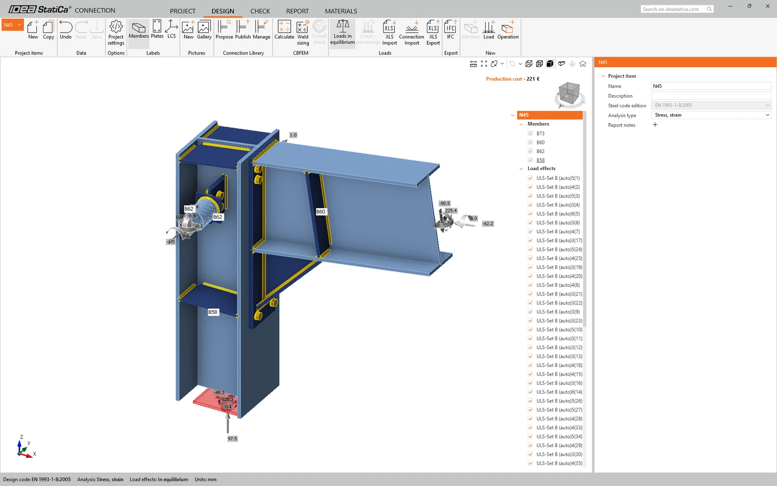
Save this connection and Close Connection app.
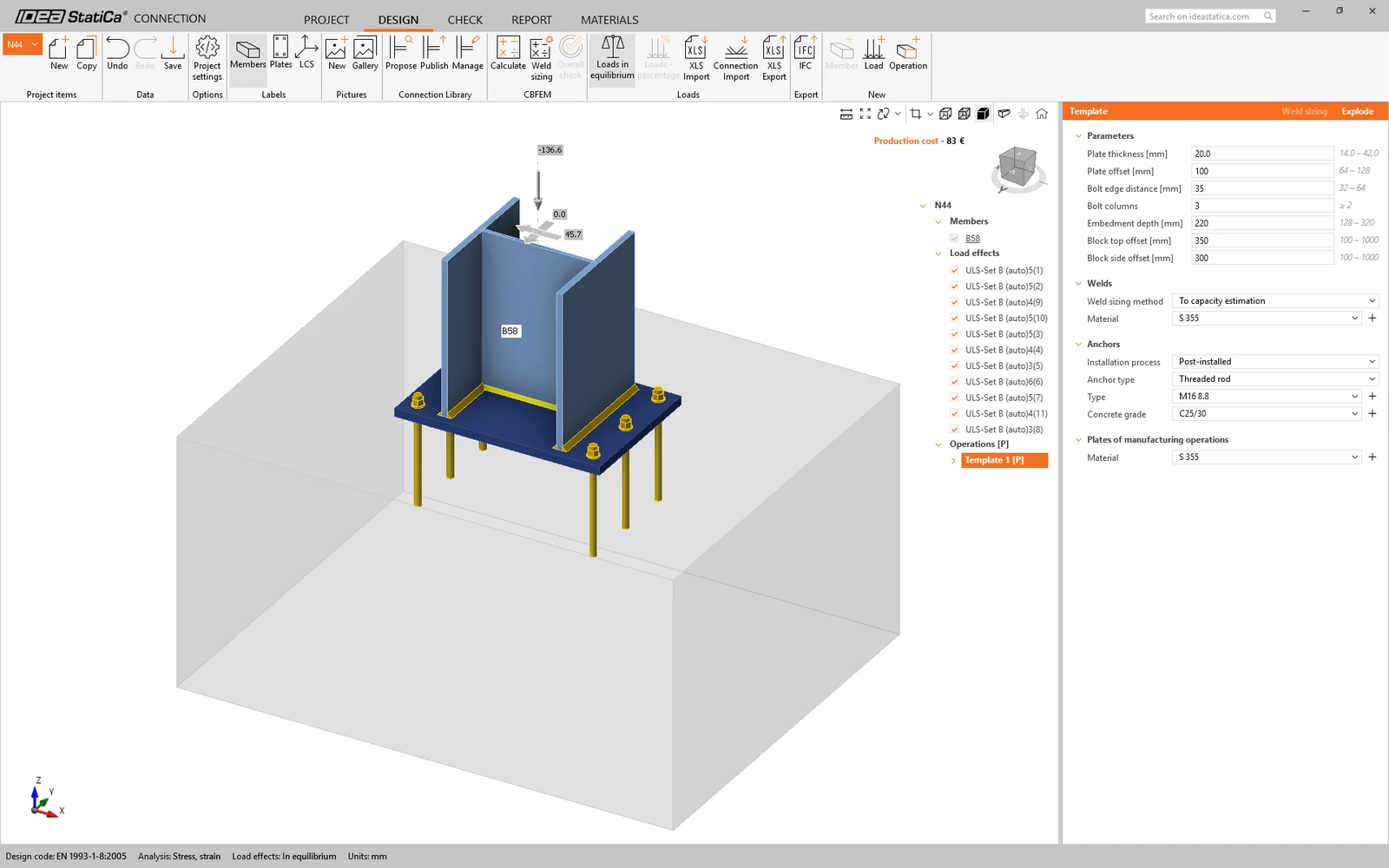
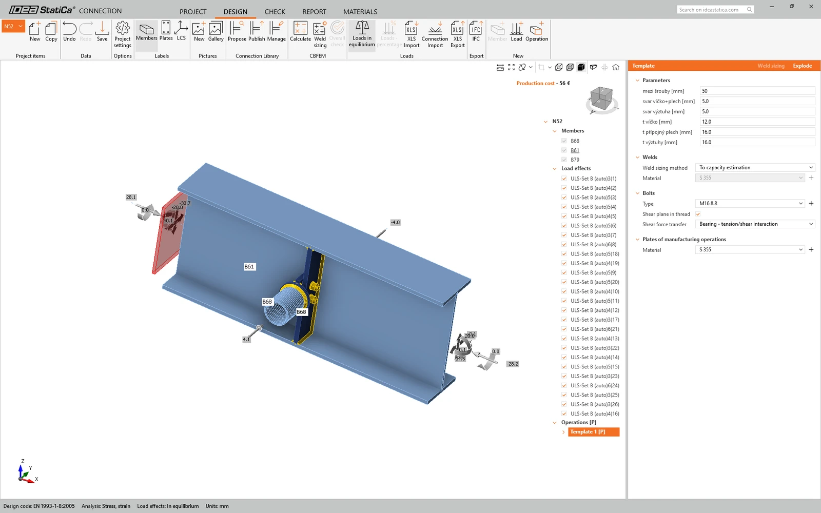
Repeat the same process to design all remaining connection groups.
IDEA StatiCa Stability
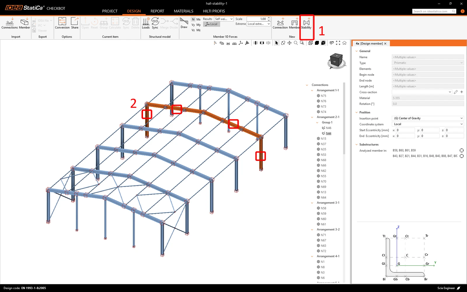
Create a new Stability project, select the members of the frame, and confirm.
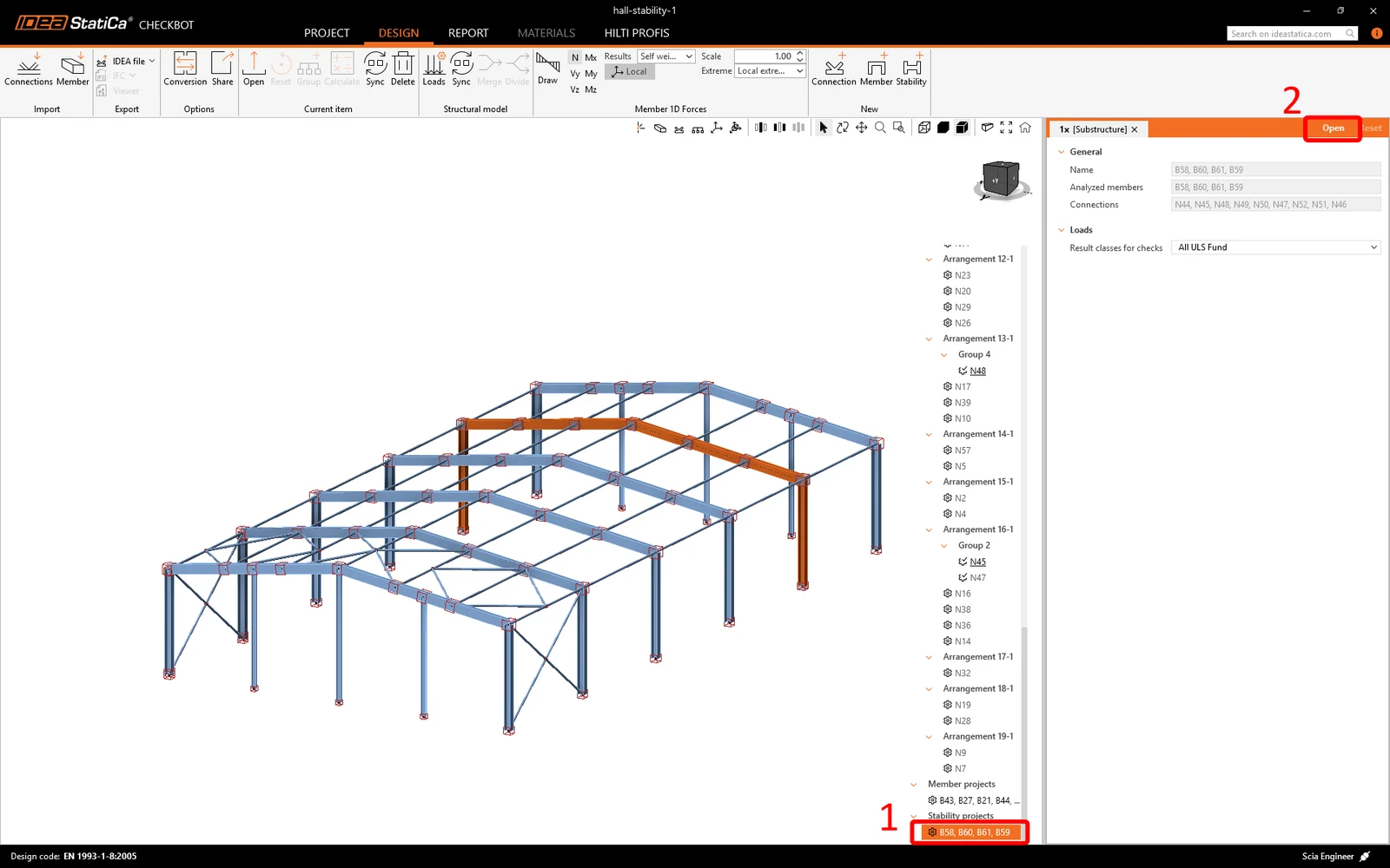
Select the project in the tree menu and click Open.
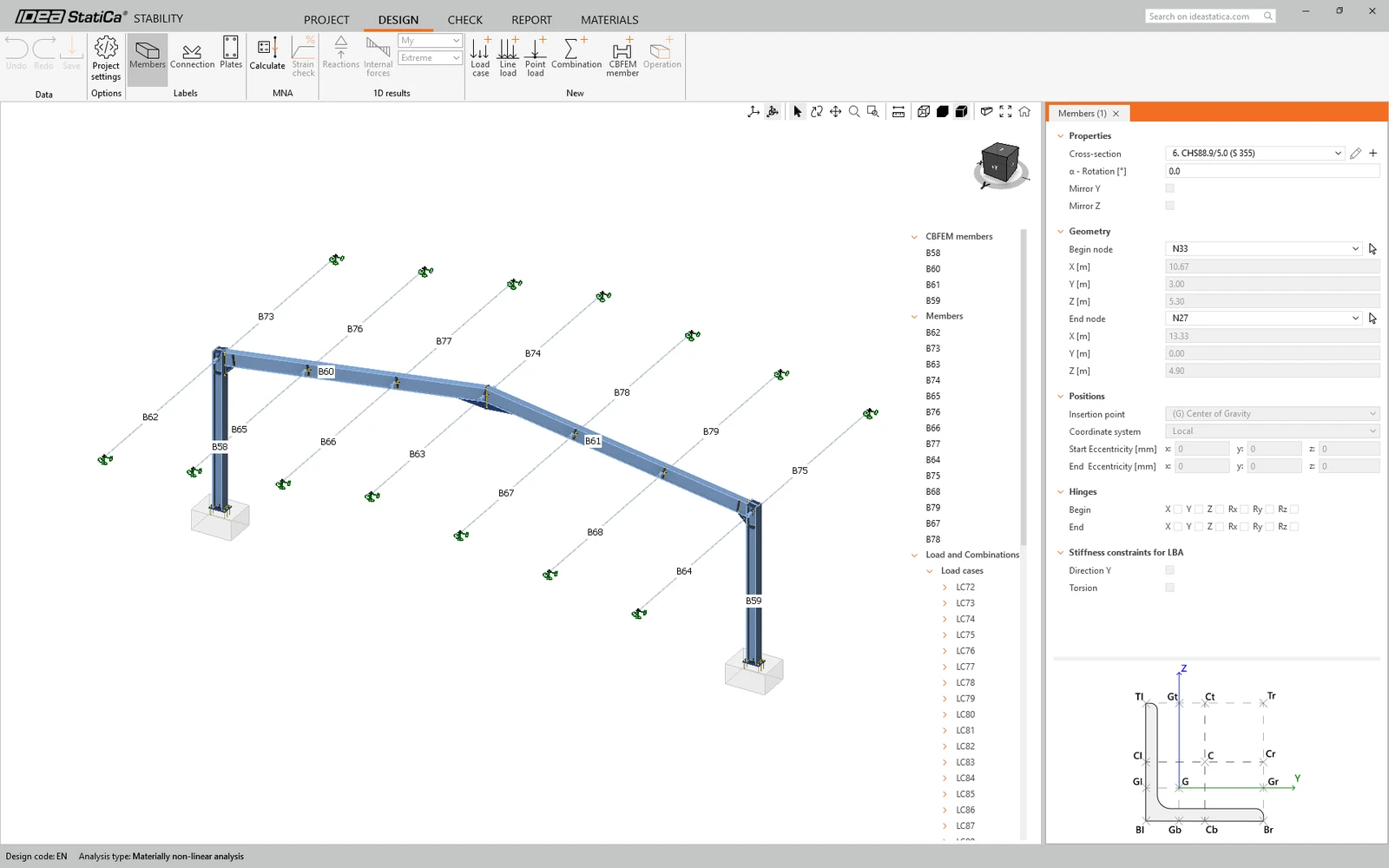
IDEA StatiCa Stability opens. You can see that, together with the CBFEM members of the frame, the connected members have also been imported.
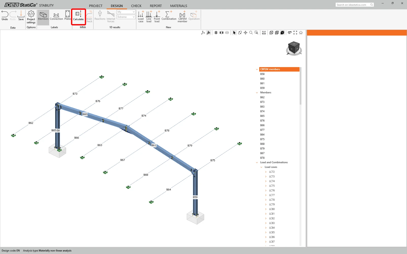
Run the materially nonlinear analysis MNA by clicking Calculate. For the purpose of this tutorial, uncheck all load combinations except ULS – Set B (auto) 5 min 5. This keeps the calculation time short.
If you want to now more information read article Types of analysis in Stability.
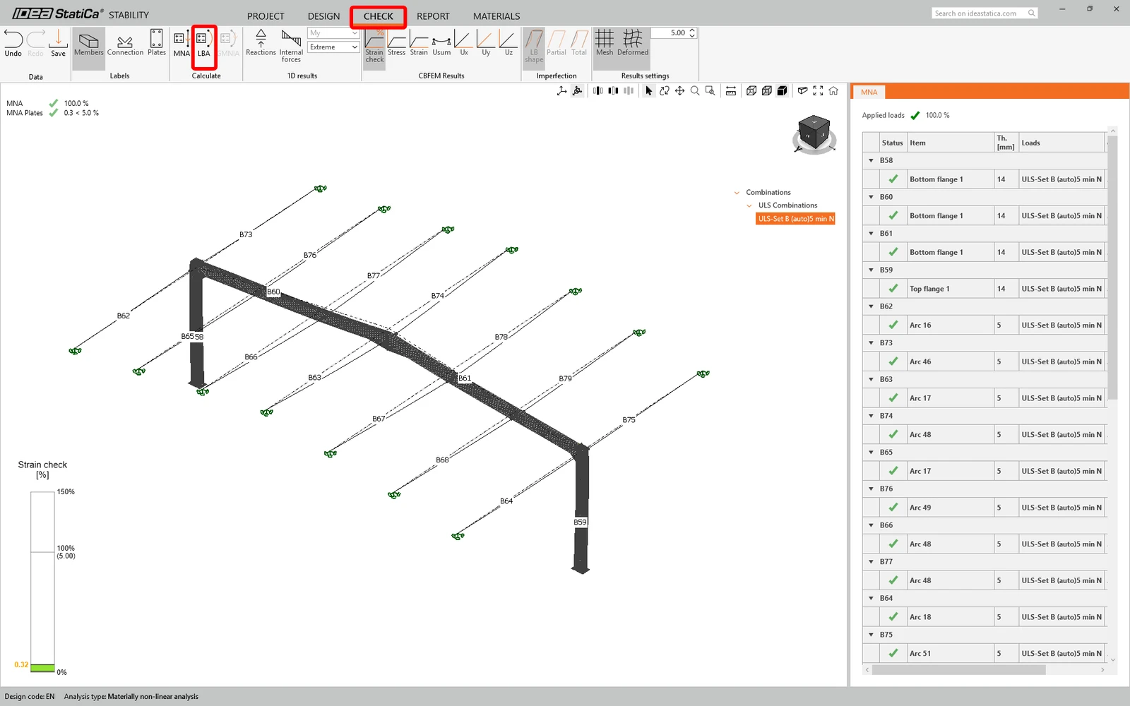
After the calculation has finished, run the LBA (Linear buckling analysis).
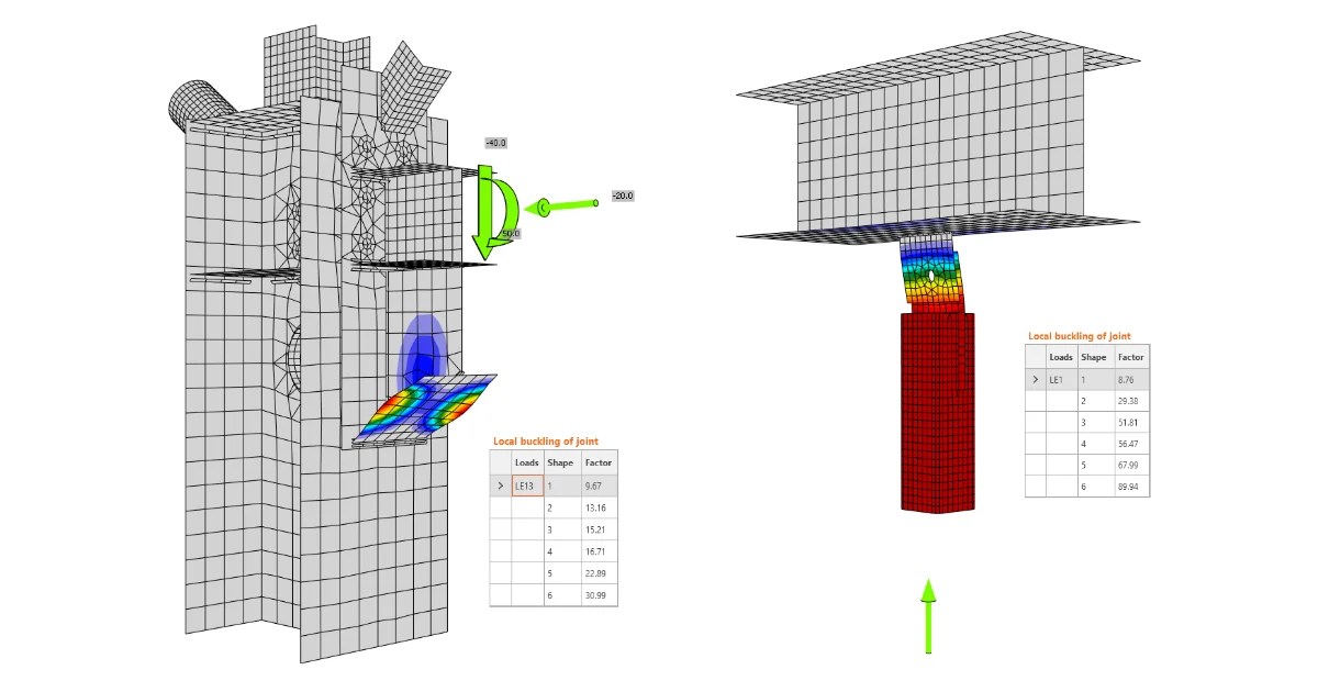
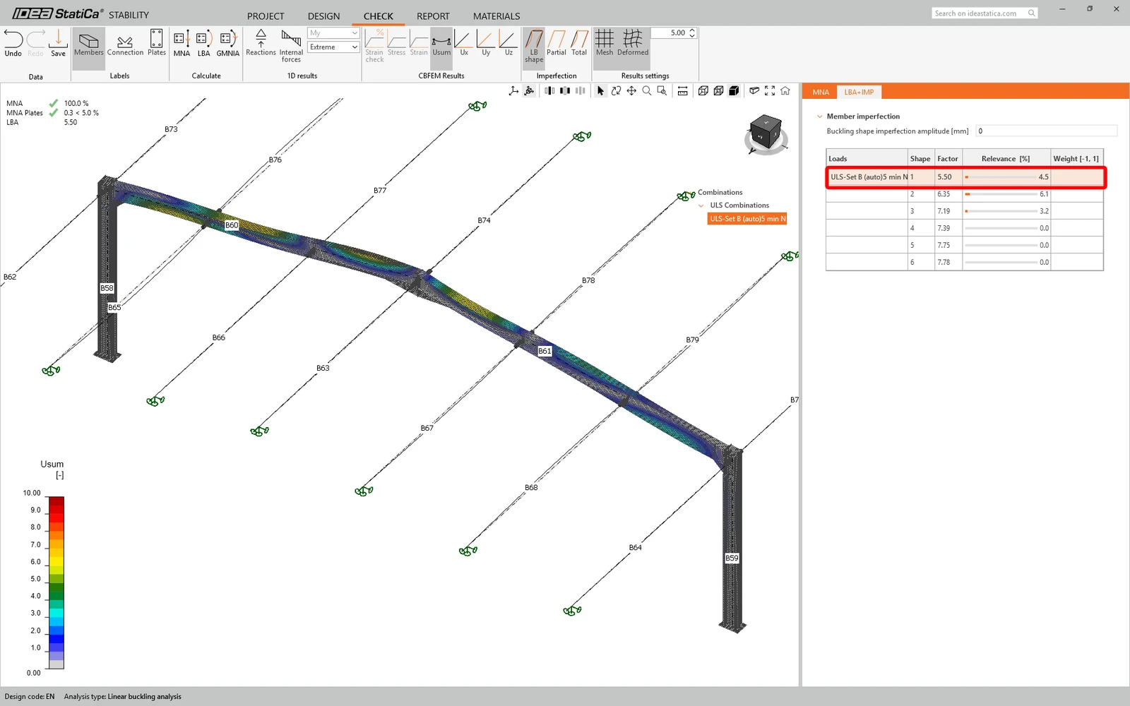
The LBA results are the buckling mode shapes and their critical load factors. You can review the buckling shapes one by one by selecting them in the table.
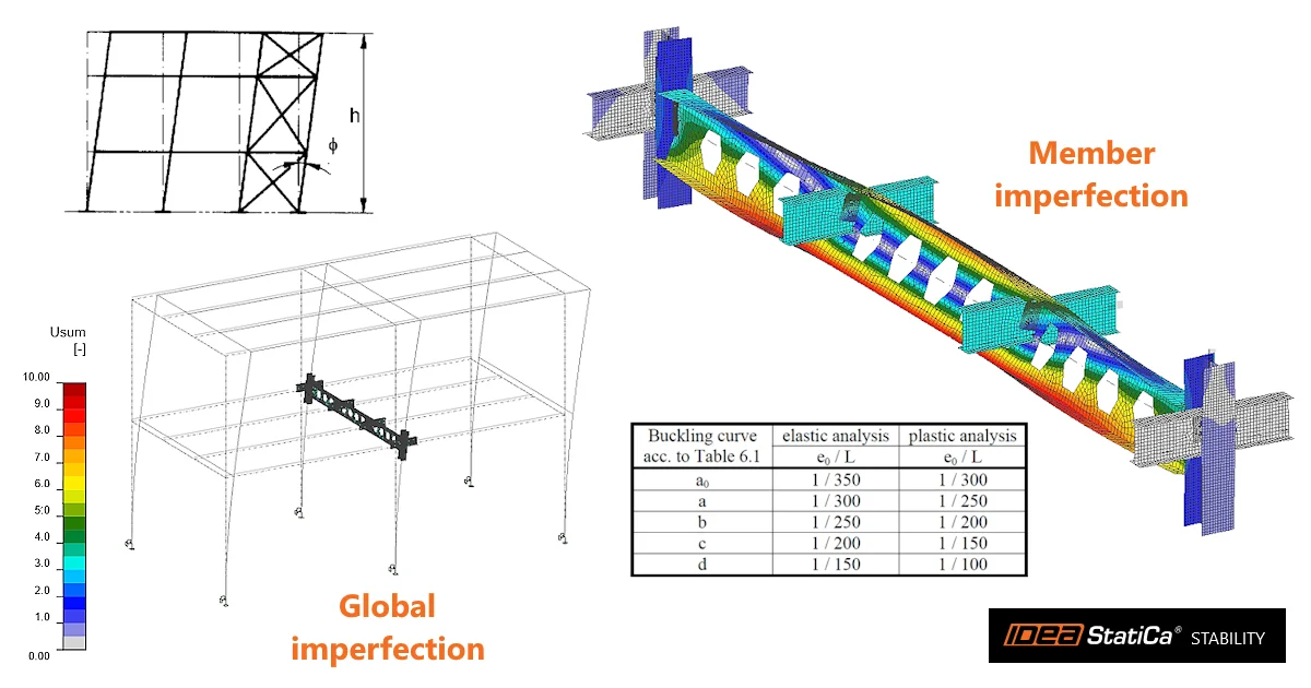
Now you can select the buckling shape to which you will apply the imperfections and perform GMNIA (Geometrically and materially nonlinear analysis with imperfections). Enter the imperfection amplitude e0 and run the analysis. Read more about imperfections in How to input imperfections in Stability.
Imperfection used e0 = L/200 = 80 mm (with conservative value of L = 16 m as the span of the frame).
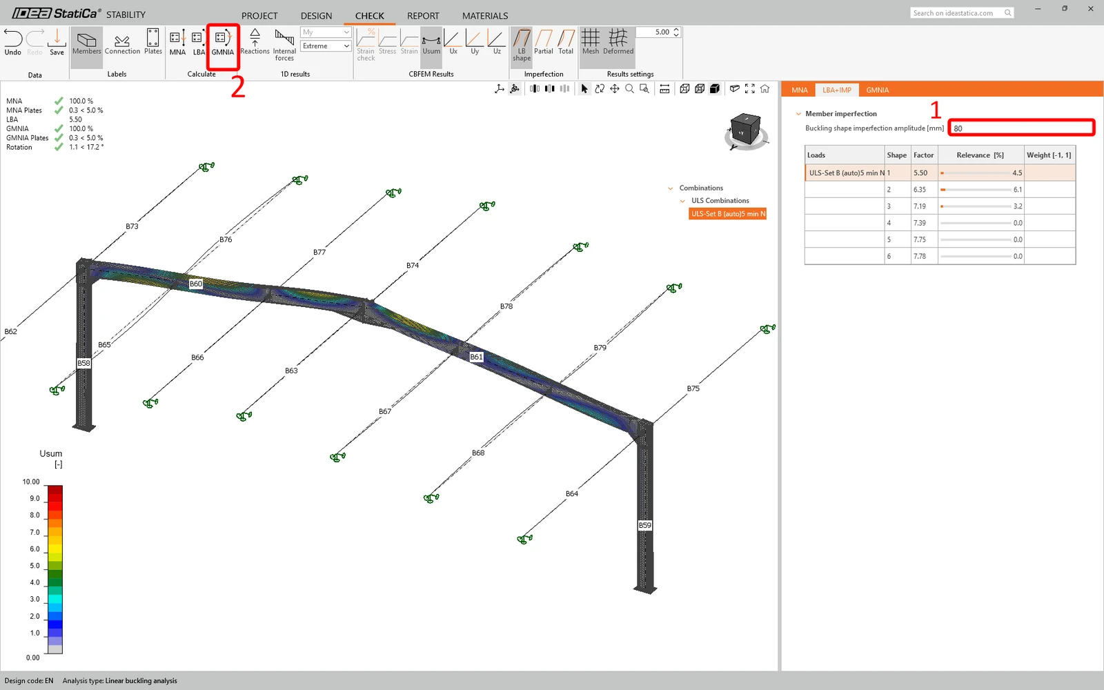
Based on the results from GMNIA we can say that the frame passed the code-checks with applied initial imperfections and we can see the results such as stress distribution and internal forces diagram.
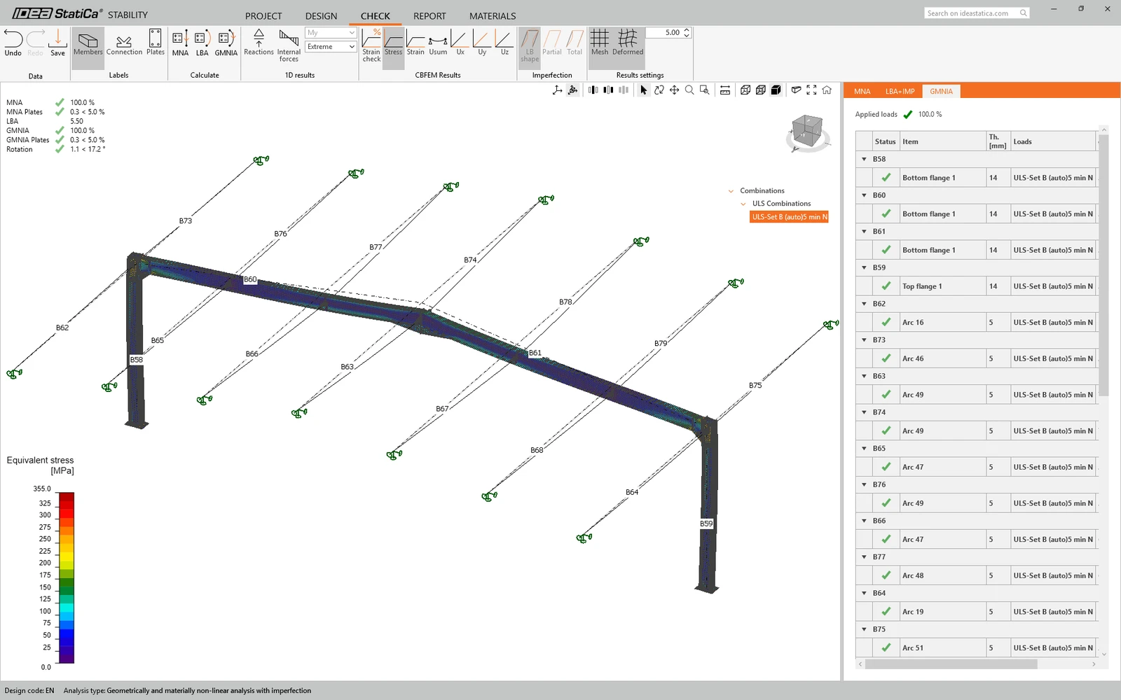
You have successfully linked SCIA Engineer with IDEA StatiCa Stability via Checkbot.
Read more about the known limitations for SCIA Engineer BIM link.
Alternative workflow: Exporting a Stability project from Checkbot
You can use IDEA StatiCa Checkbot purely to import the structure and loads into the Stability app. The advantage of this workflow is that the entire hall is modeled in the Stability app, so the calculations take the stiffness of the whole structure into account. You can also review the internal forces from the linear analysis directly in the Model tab of the Stability app.
In the newly imported structure in Checkbot, create a Stability project containing all members.
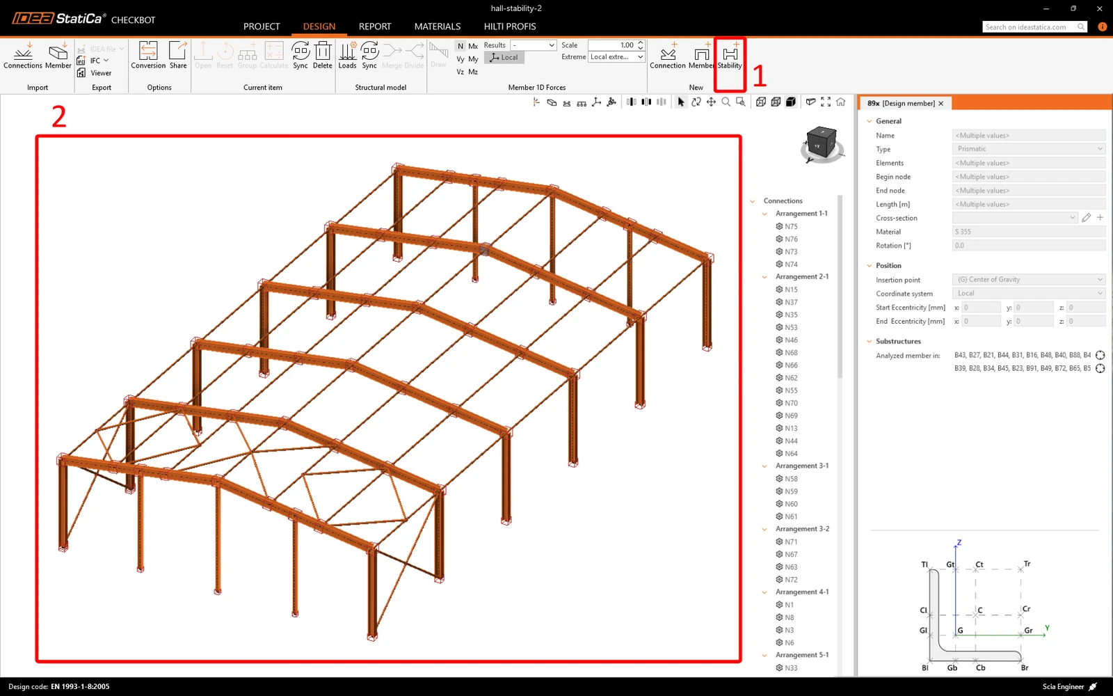
Right-click the Stability project and select Export.
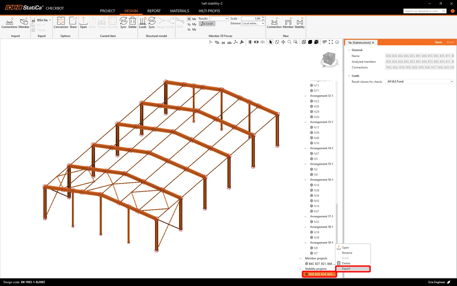
A ZIP file will download to your computer. Extract it, then open the extracted folder in the IDEA StatiCa Stability app.
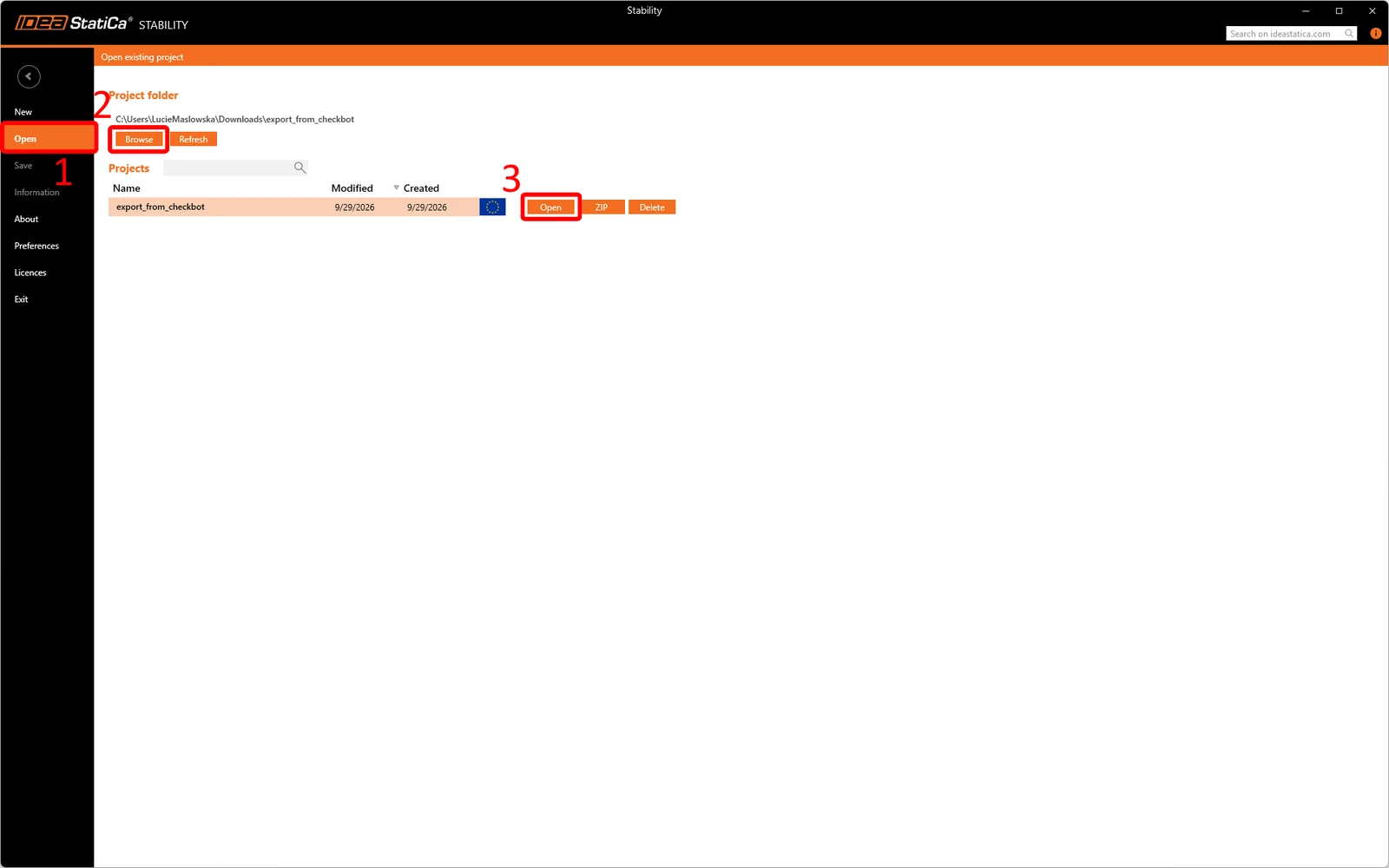
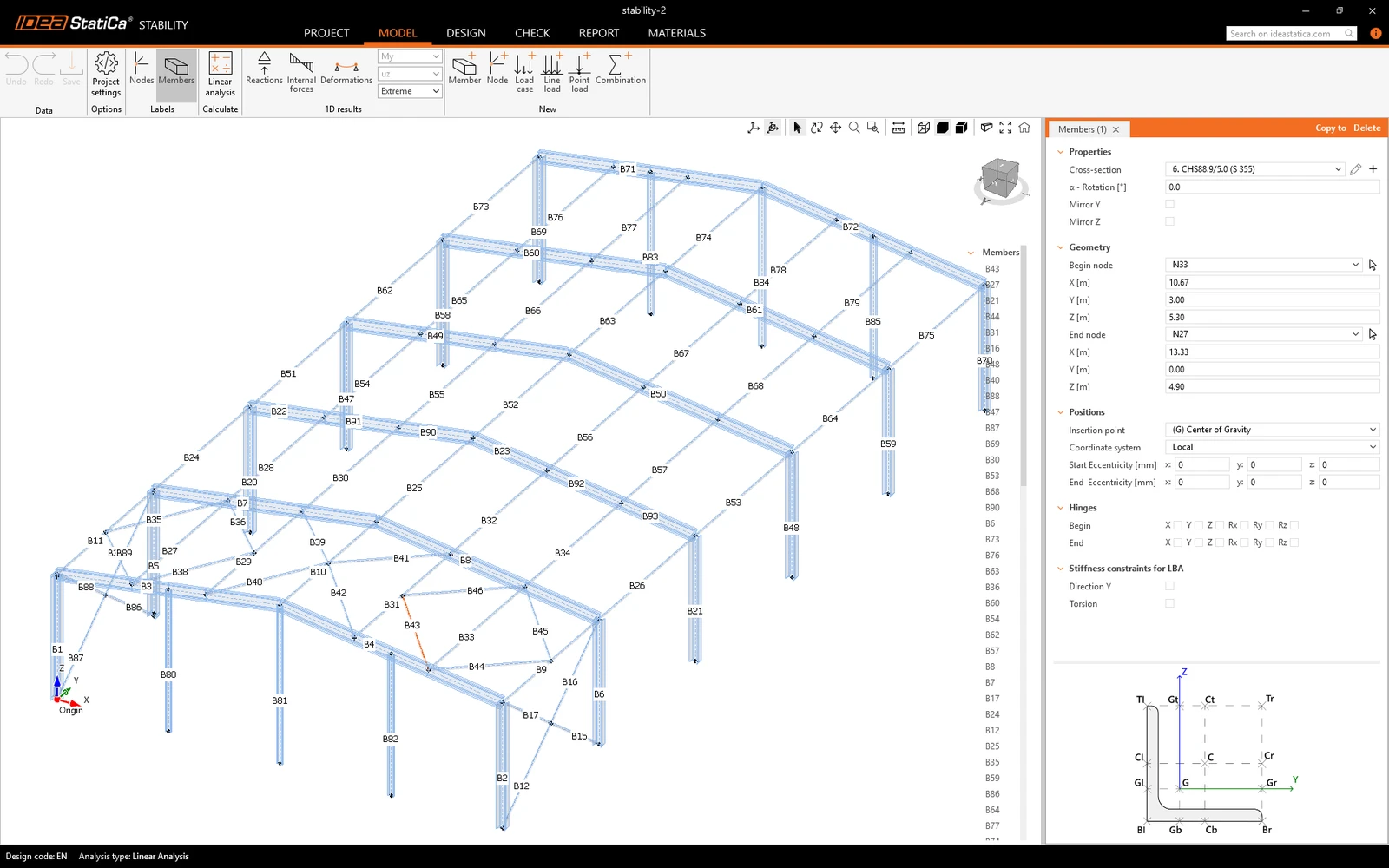
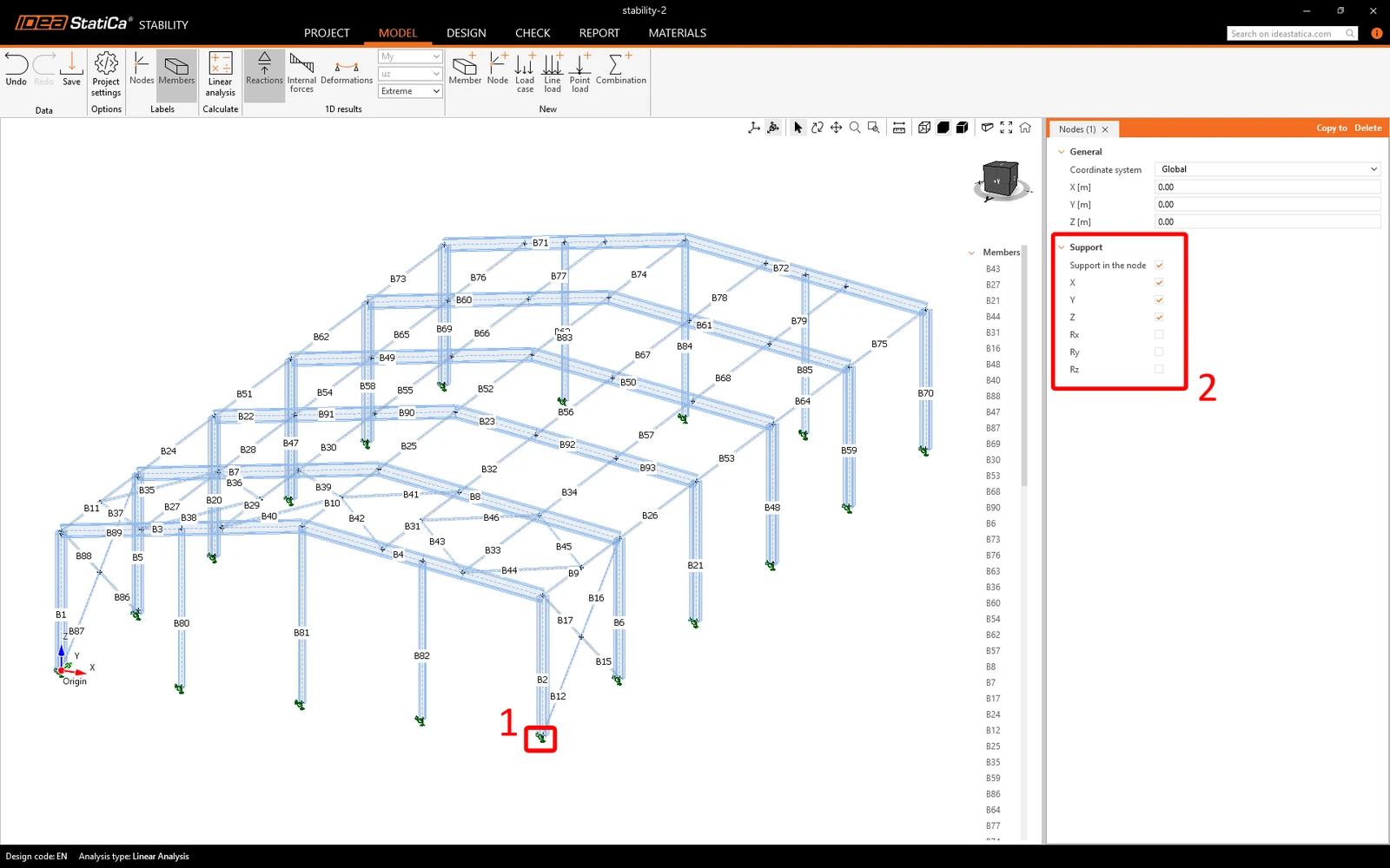
Only the structure and loads are imported into the Stability app, so you need to add supports yourself. Do that for all of the columns.
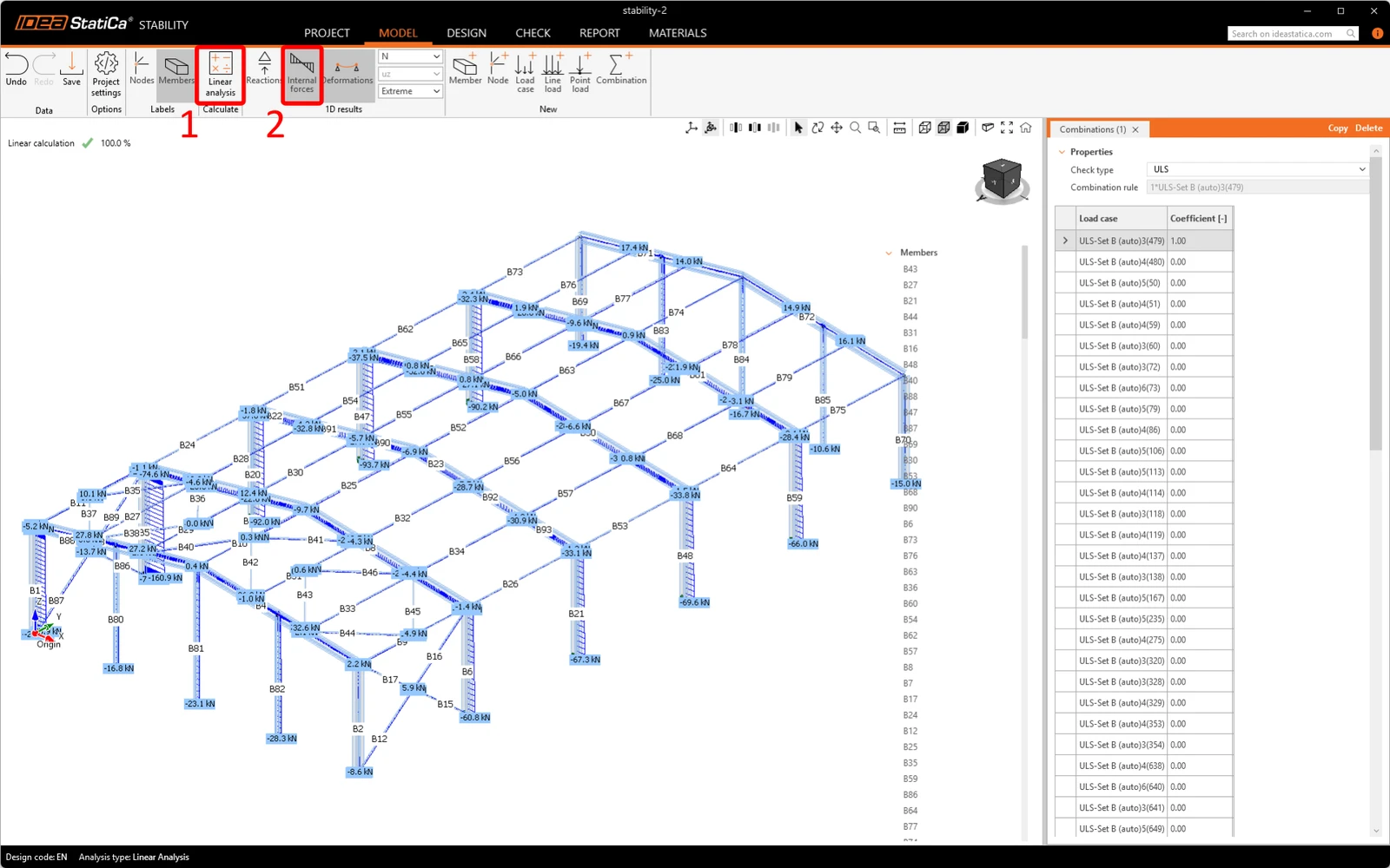
Now run the Linear analysis and review the results.
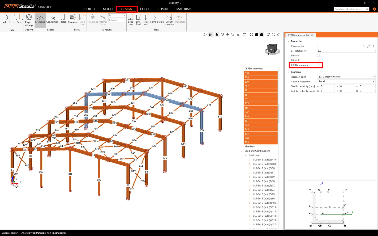
For check only one frame rather than the whole structure, go to the Design tab, select all members except those in the frame, and uncheck the CBFEM member box.
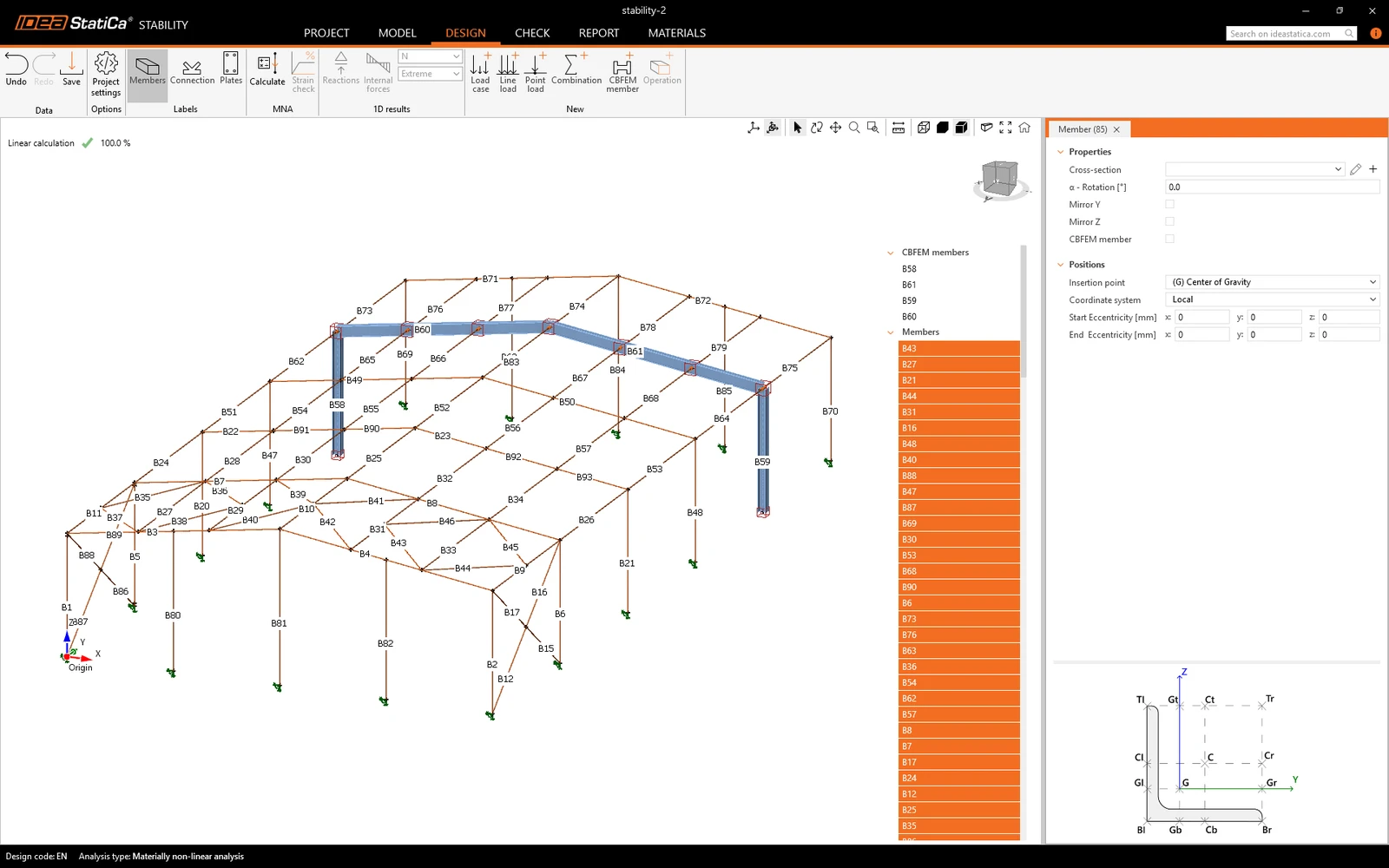
Finally, design the connections. Select one and Open it in Idea StatiCa Connection.
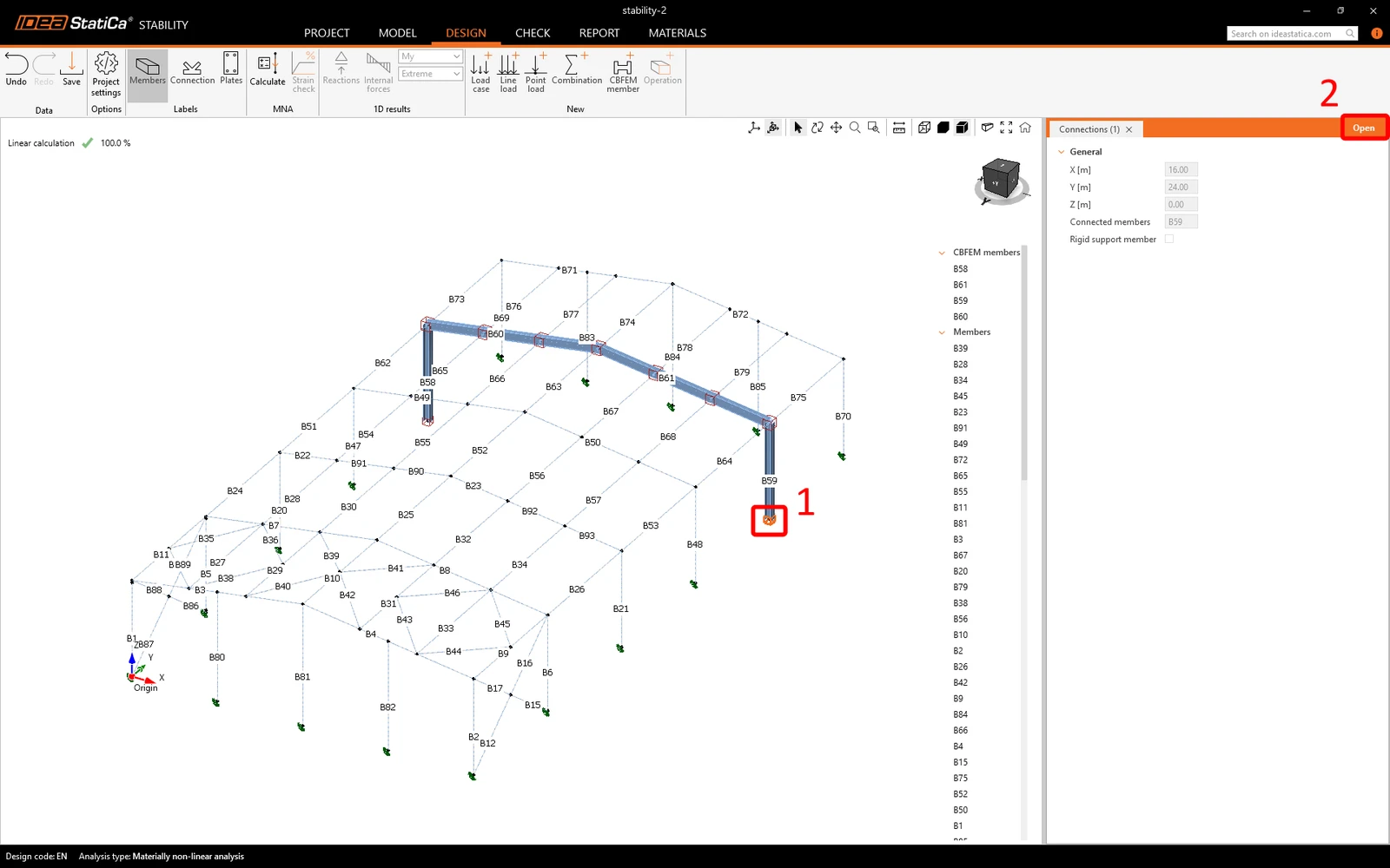
After designing a connection, close and save it. When you then select an undesigned connection with the same geometry, you can easily Apply the design from the previous connection.
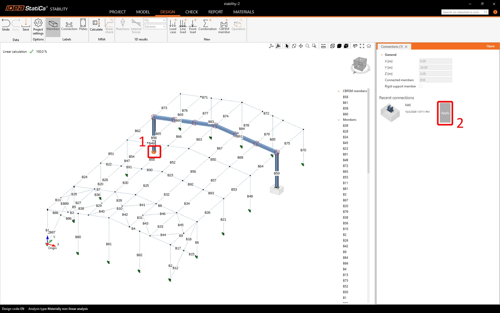
To finish the design, repeat this for all connections in the frame.
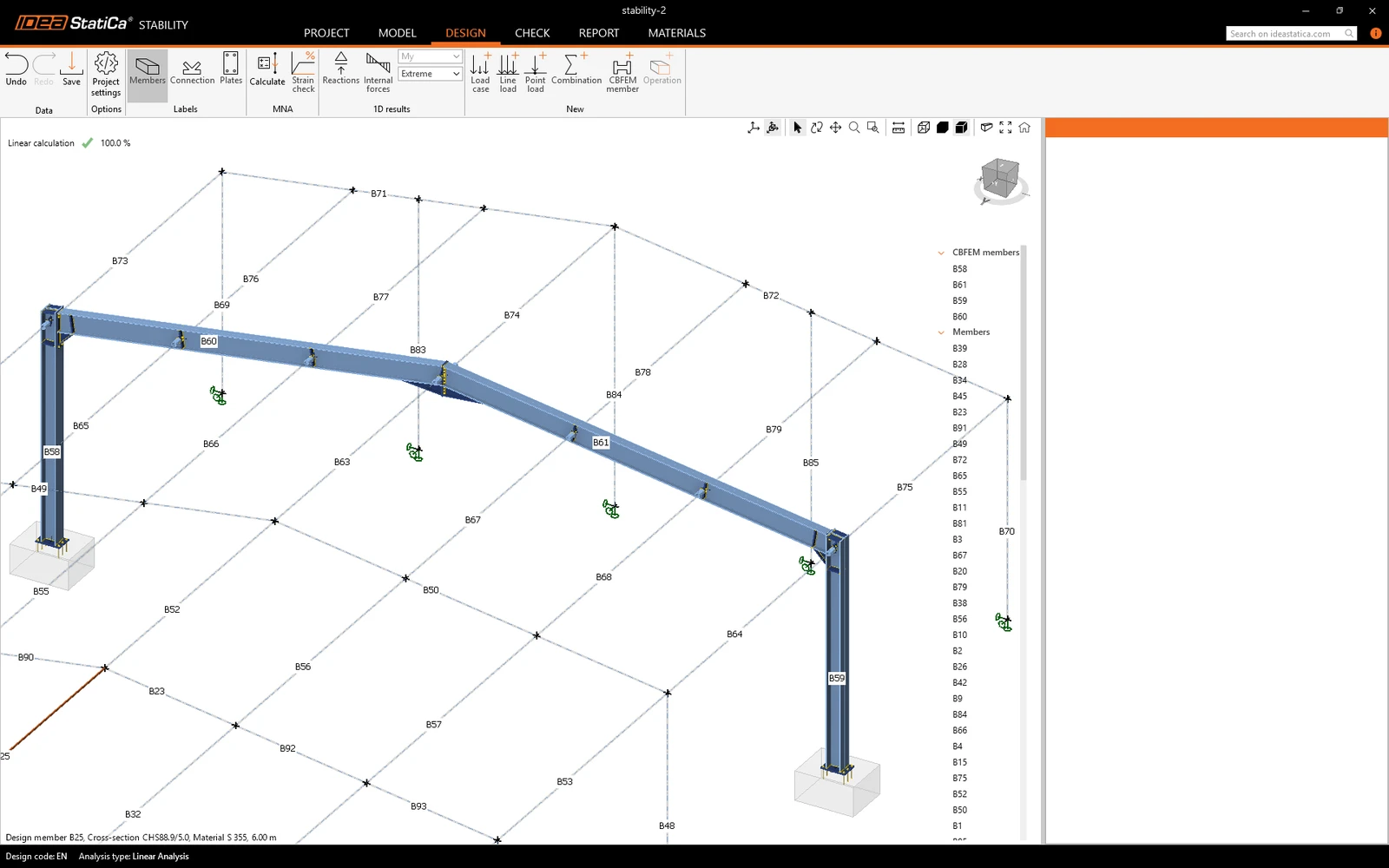
You can now continue with the analysis as described earlier in this tutorial.
Want to improve your skills? Visit our Campus
Learn how to use IDEA StatiCa effectively with our self-paced e-learning courses
Start learning