New project
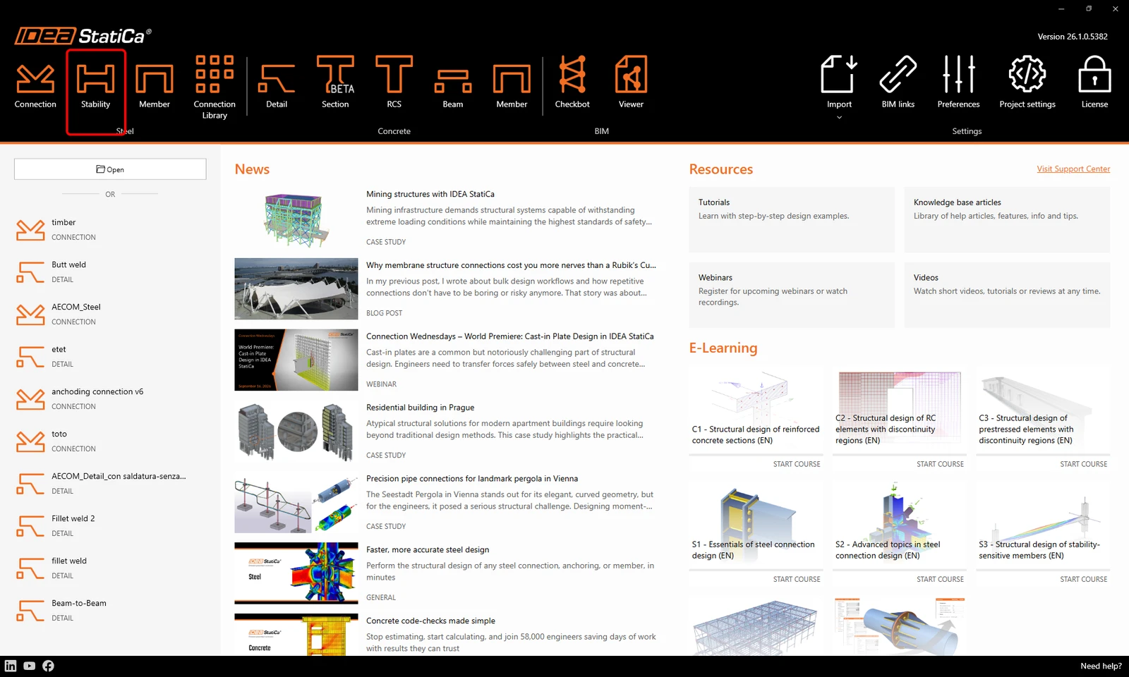
Start by opening IDEA StatiCa and selecting the Stability application (download the latest IDEA StatiCa version).
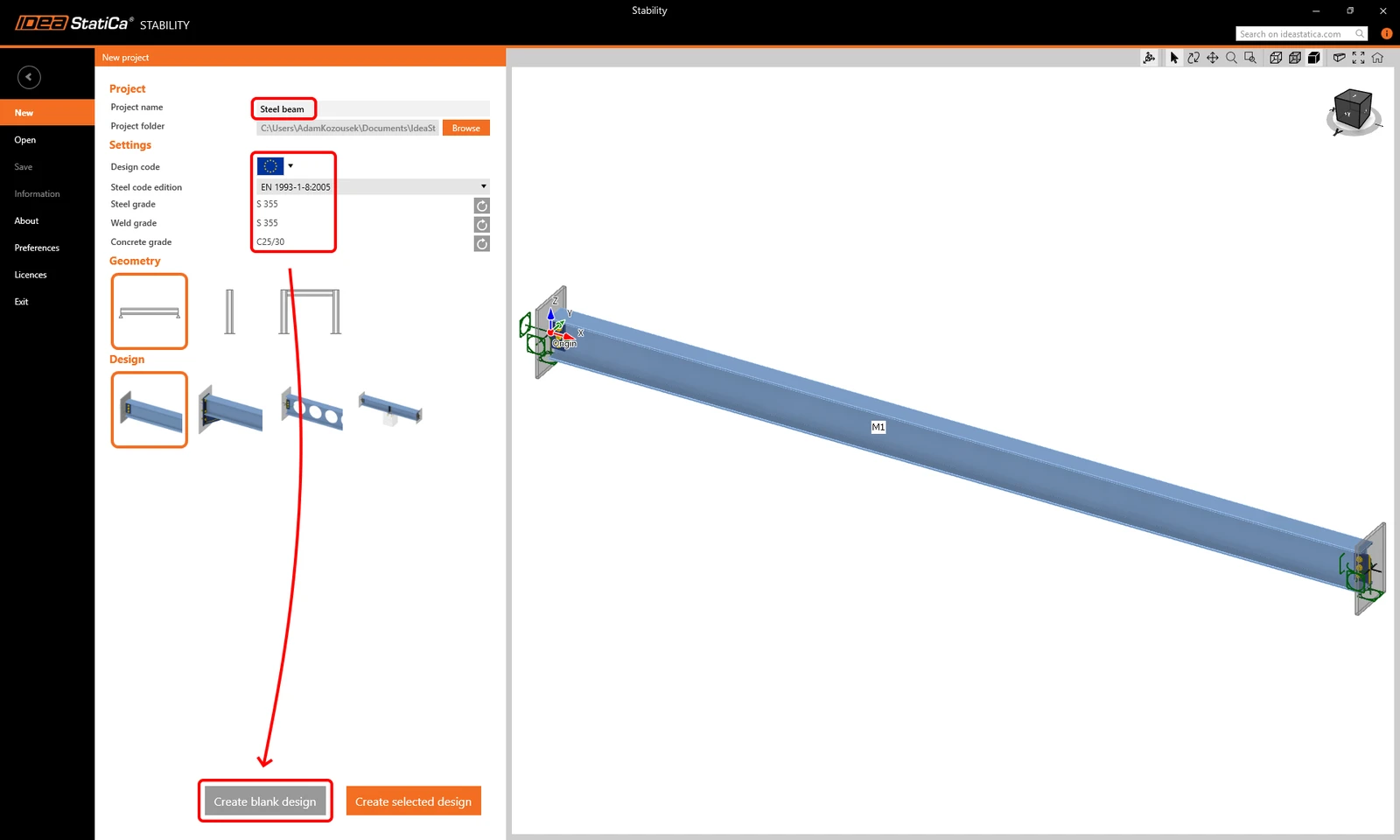
As the first step, you create a New project. You need to type in the Project name, and then you can define the default settings of your project - select Eurocode as the Design code and the Steel code edition EN 1993-1-8:2005. The default materials will be Steel grade S 355, Weld grade S 355, and Concrete grade C25/30.
You can change all settings of the created project later, except the chosen Design code.
You can select a starting template with predefined structural models of various geometries, or start with an empty project from scratch. Click on Create blank design to start with an empty project.
Model
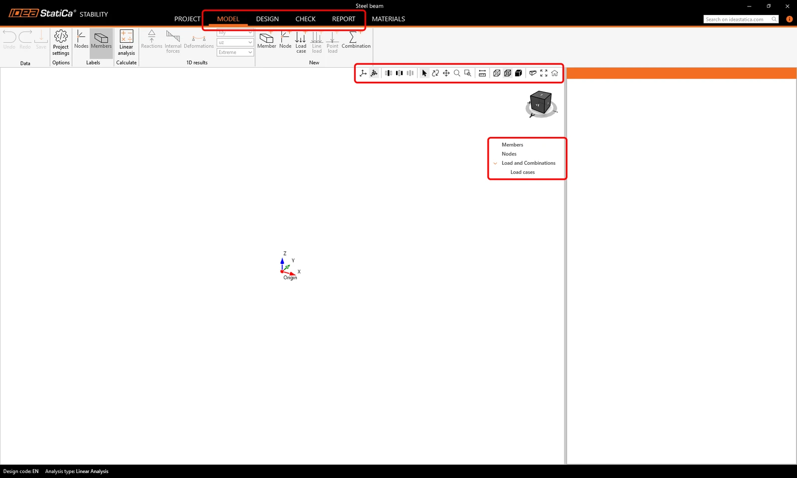
A new project was created. In the top ribbon, you can find different tabs that will lead you through the whole workflow – from Model to the Report. To control the model in the 3D scene, use your middle mouse button, Ctrl key, and the view control icons.
You start in the Model tab, where you just follow the "tree of items" in the 3D scene.
First, you need to input 1D elements to create the model of the substructure or the whole structure.
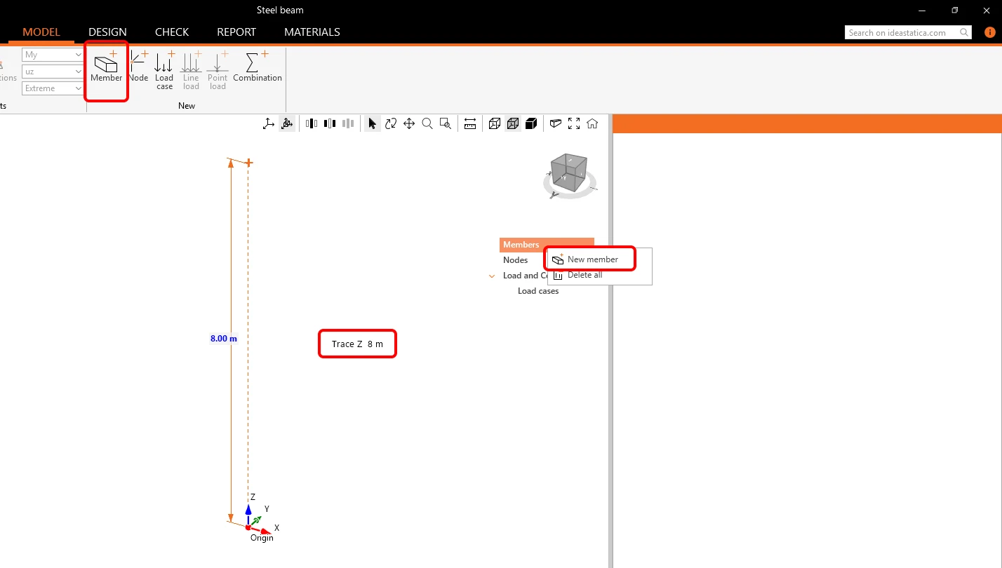
Click on the Member icon in the ribbon or right-click on the tree menu Members and add a New member. Click in the 3D scene to define the begin node of the new member in the global origin [0;0;0]. Move your mouse above this point in the direction of the Z axis and type 8 on your keyboard to draw a column 8 meters high. Confirm by a mouse click or pressing Enter.
A default cross-section HEA400 and material S 355 were automatically assigned to this member.
Right-click on column M1 in the 3D scene and select Copy to (or press Ctrl+C or click on M1 in the tree list or on the command Copy to).
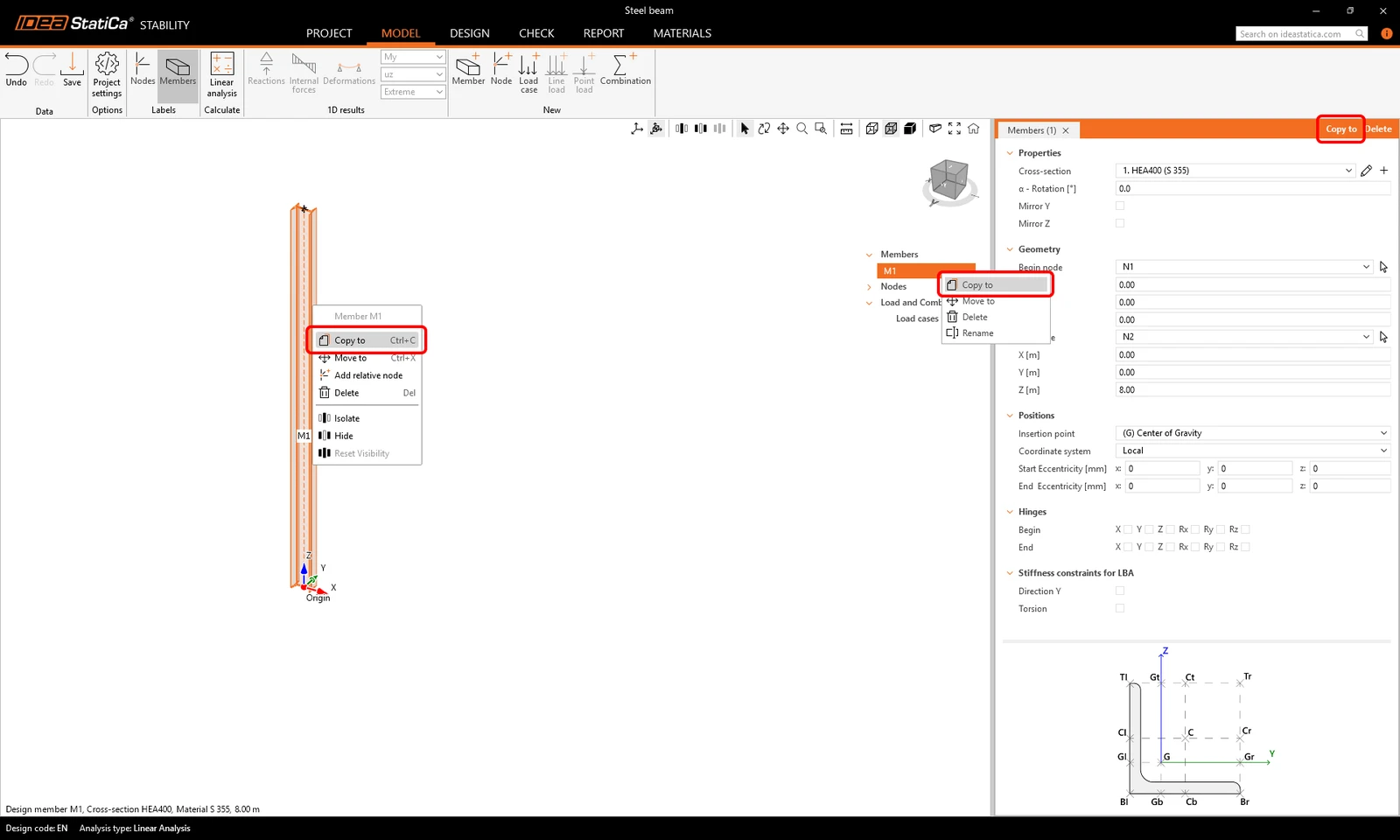
Then select the begin node of the column M1 as the Reference point. Move your mouse in the direction of the global X axis (to the right of the column) and type 6 on your keyboard to copy the column a distance of 6 meters, and confirm by a mouse click or pressing Enter.
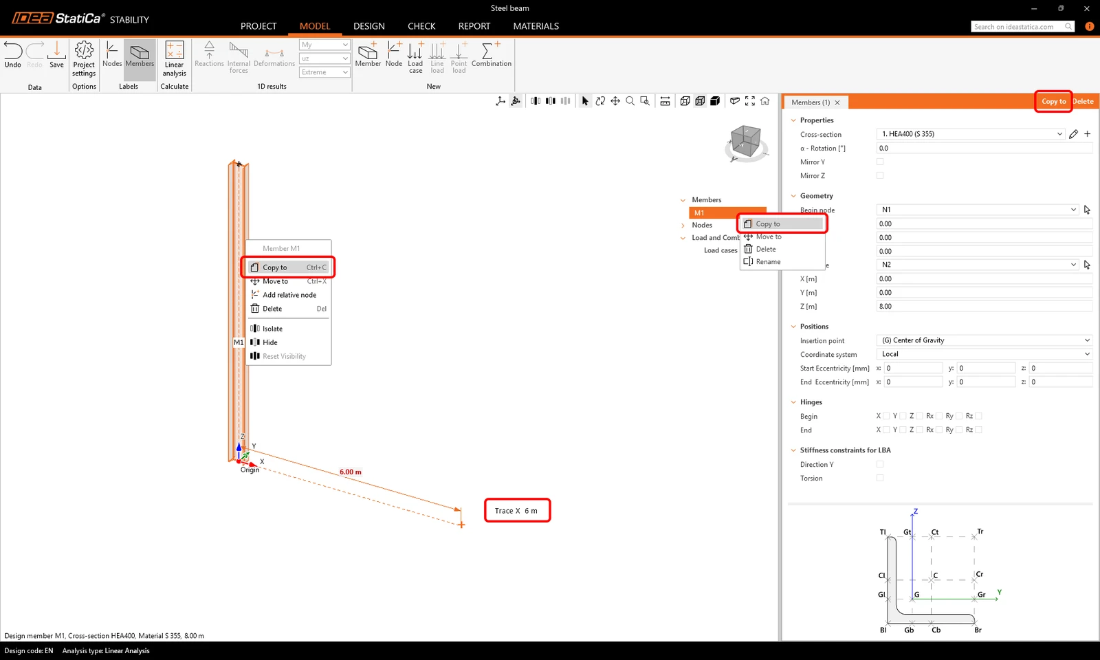
Then press Esc to stop making other copies of the column.
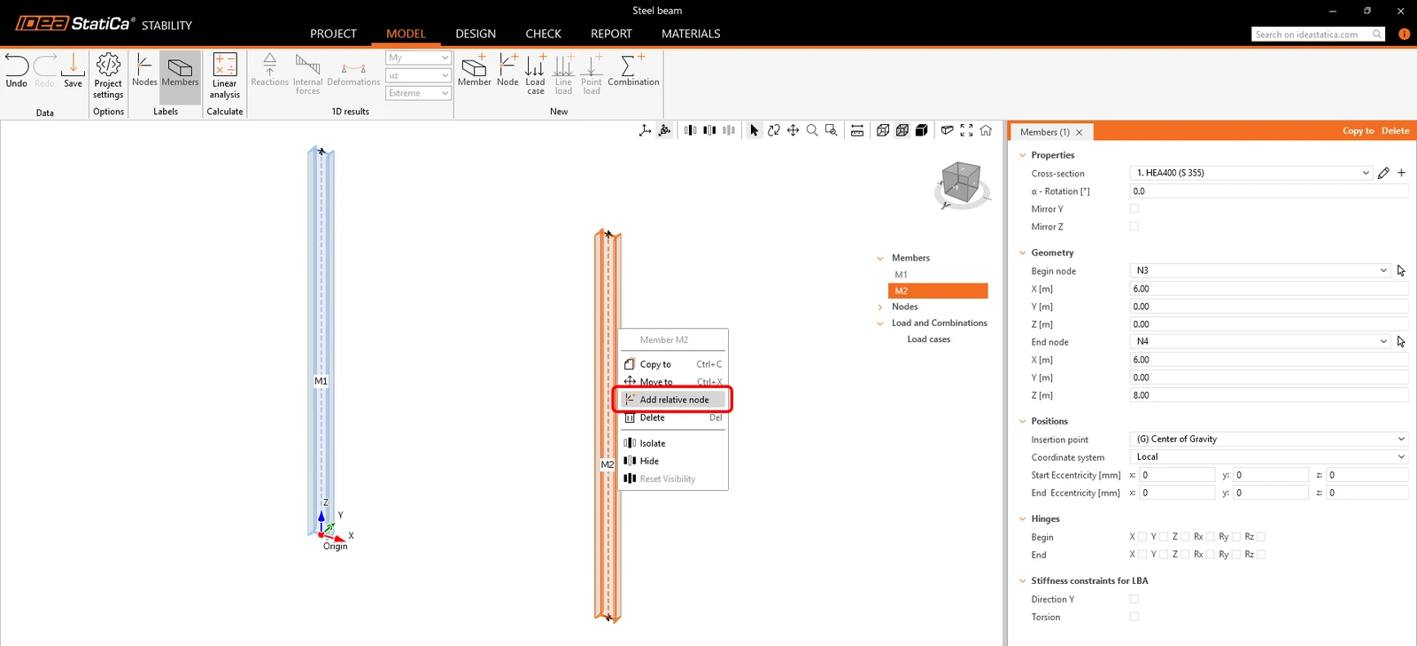
Right-click on column M2 and select Add relative node. This node is automatically placed in the middle of the column length. Repeat the same with column M1.
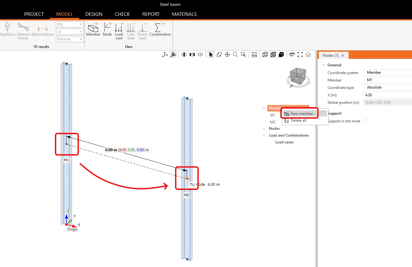
Add a New member again. Select the relative node in the middle of the left column M1, and then the other relative node in the right column M2.
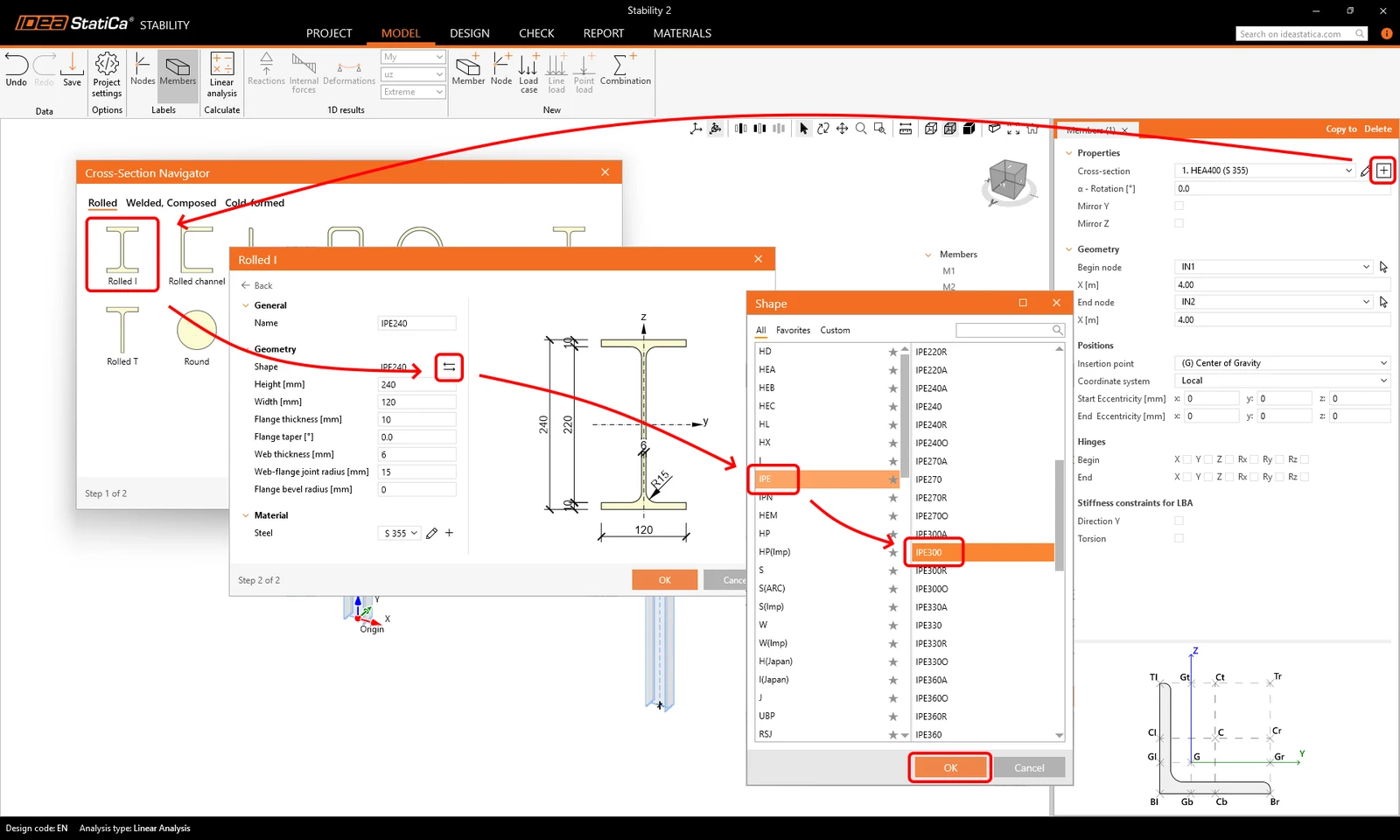
Change the cross-section of the added beam M3 by clicking on the + button. Select the type Rolled I and next to the parameter Shape, click on the arrows button. Shape library opens, select IPE 300, and confirm OK in all windows.
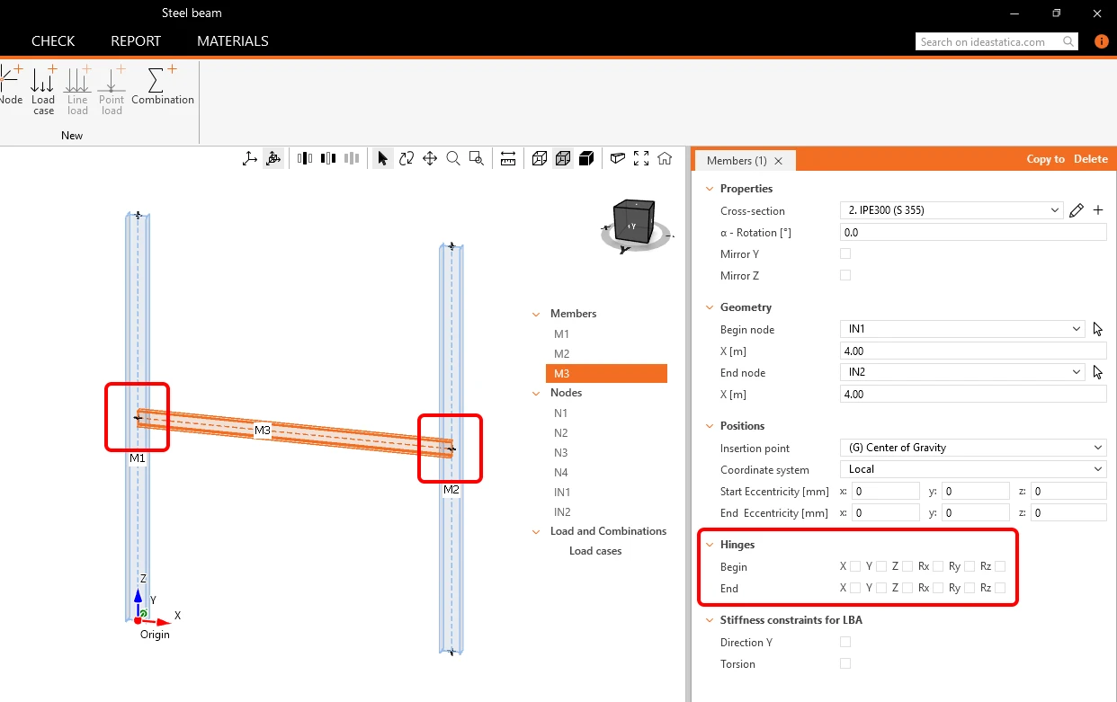
Next, you define the support and hinges in the substructure model. Both hinges of the beam M3 are set by default as rigid (no degrees of freedom are released in the properties), so keep this default settings
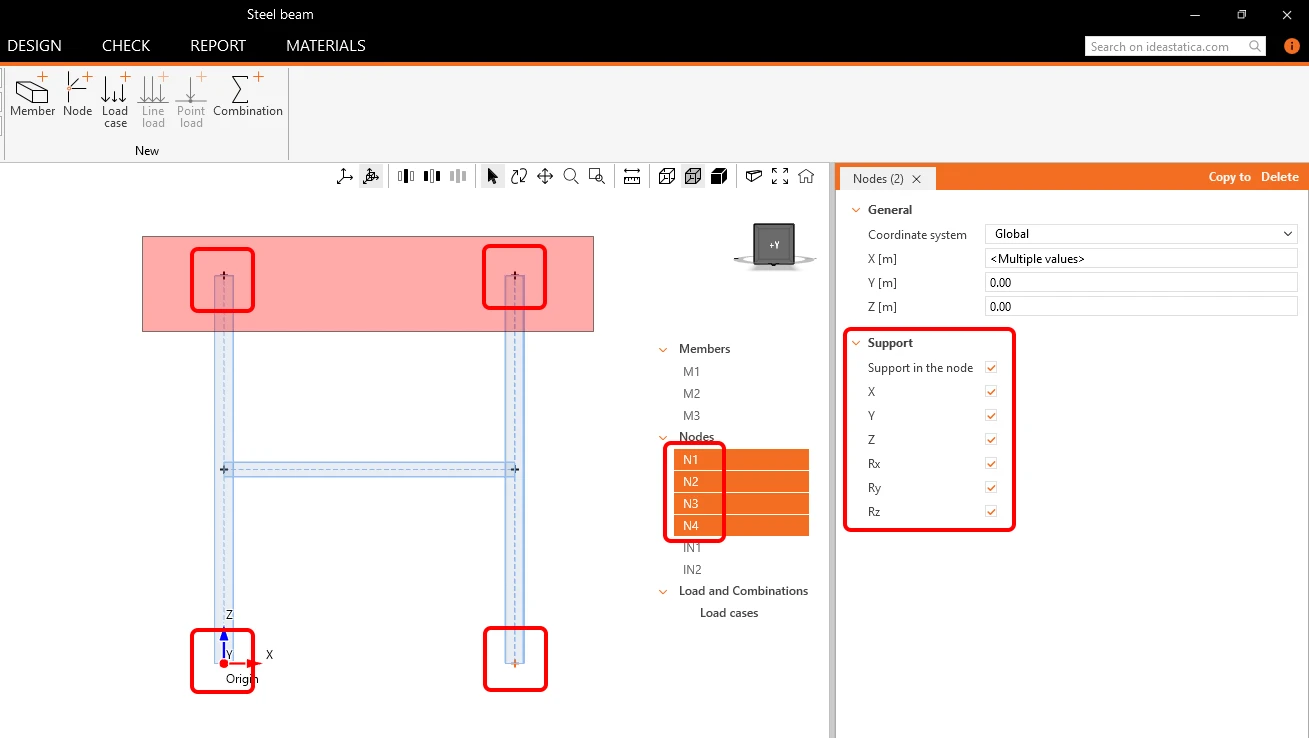
To add supports to the columns' ends, select the nodes by dragging the mouse over the top two nodes and then hold Ctrl and select the bottom two nodes (or, open the Nodes list in the tree and select the nodes N1-N4). Enable Support in the node and select X, Y, Z, Rx, Ry, and Rz to add a rigid support.
- Read more about Members and modeling structures in How to create structural model in Stability.
Loads
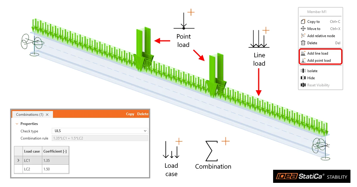
Loads in Stability are defined by load cases that can include self-weight, line loads, and point loads, and load combinations.
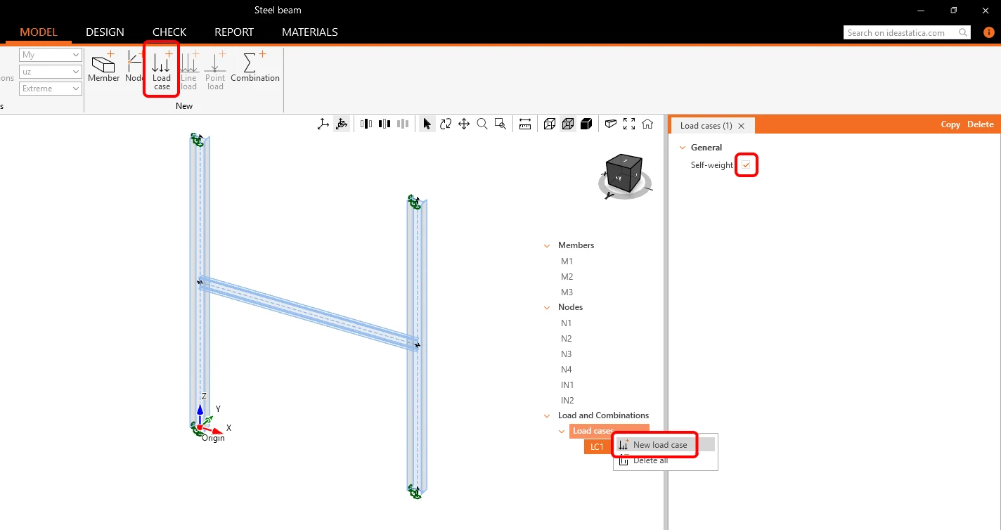
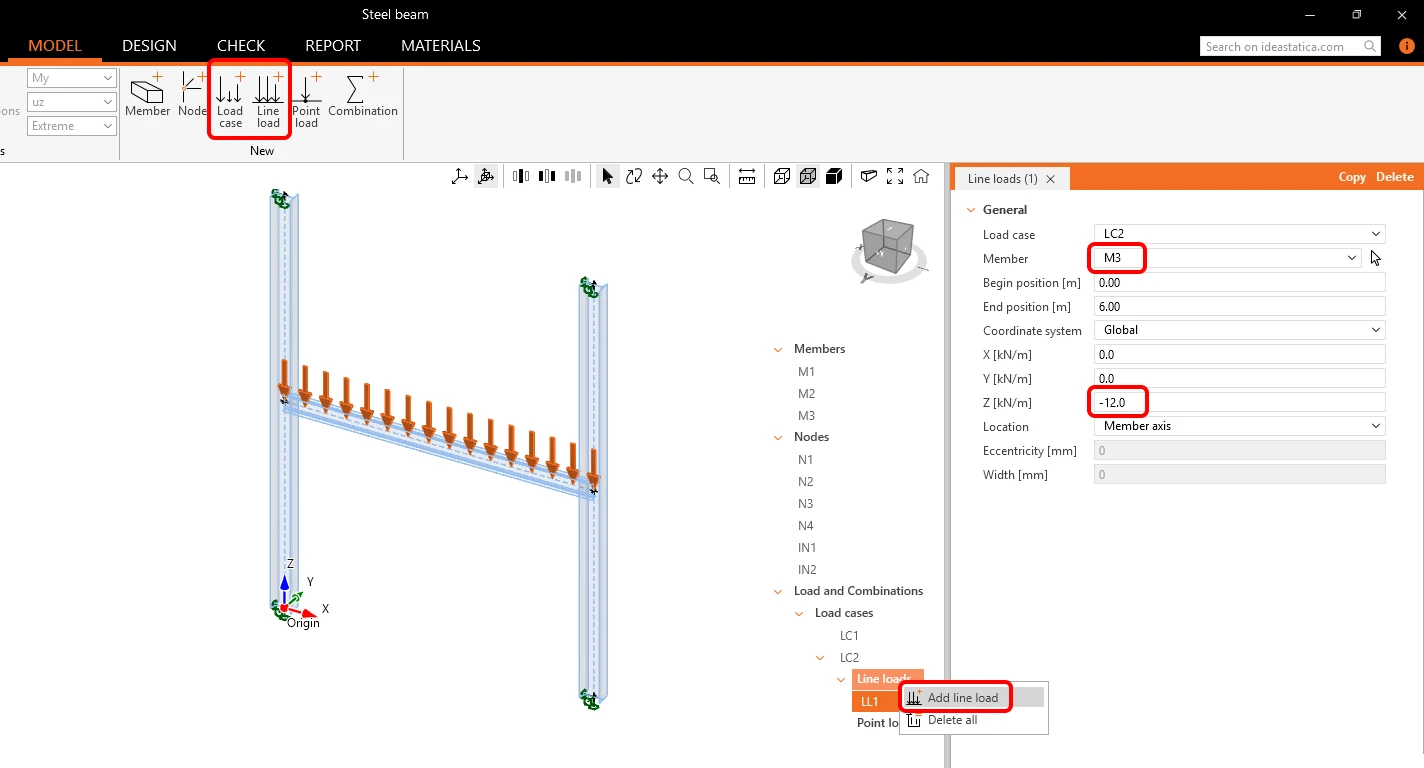
Click on the Load case in the ribbon (or right click Load cases in the tree and select New load case) to start adding loads. Load case LC1 was added since it represents the dead load of the structure, tick the Self-weight.
Add another load case LC2. With the LC2 selected, click Line load on the ribbon (or right-click LC2 in the tree and select Add line load). In the properties of LC2 change the Member to M3 (or click on the arrow button and select the beam M3 in the 3D scene). Change the load value in global direction Z [kN/m] to -12. You can set eccentricity and width for line and point loads later in the Design tab.
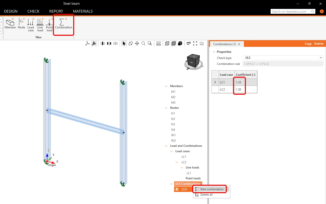
Click on the Combination in the ribbon. A load combination CO1 was added. Modify the combination Coefficient values in the tab for LC1 to 1,35 (permanent load) and for LC2 to 1,5 (variable load).
- Read more about Load and combinations in How to define loads in Stability.
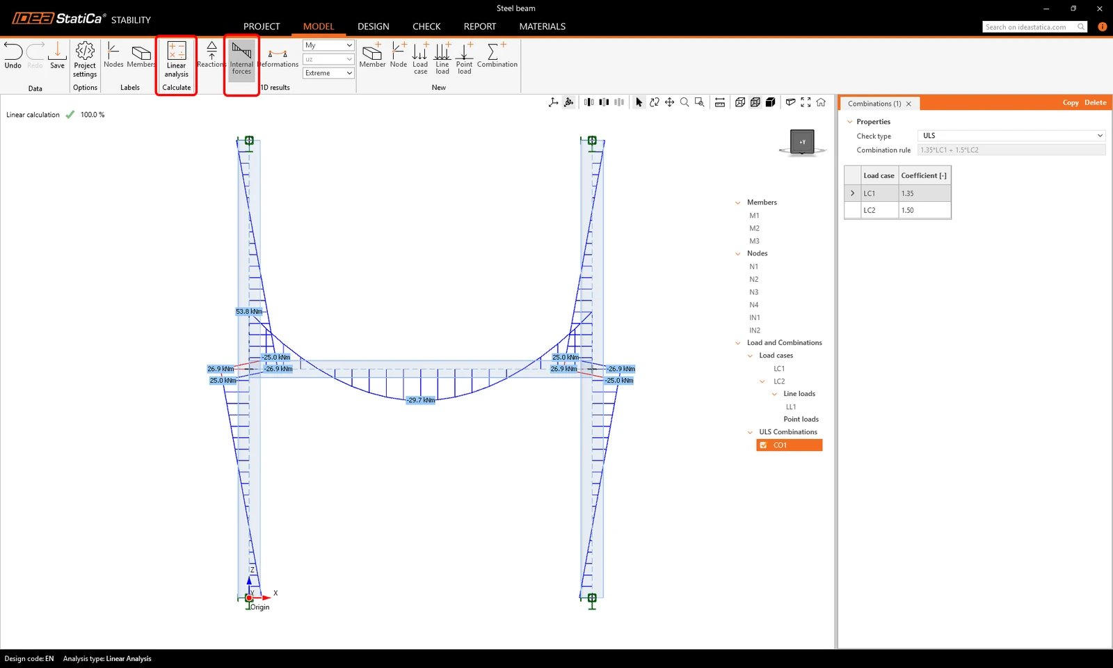
You can click on Linear analysis to calculate the substructure. Click Internal forces to display the diagrams and values of the bending moment My and other internal forces or deformations.
Design
Switch to the Design tab and define the member(s) you want to design and analyze. The rest of the substructure will work as precise boundary conditions for the CBFEM member.
Click CBFEM member in the ribbon and select the beam M3 (or select M3 in the tree and tick CBFEM member).
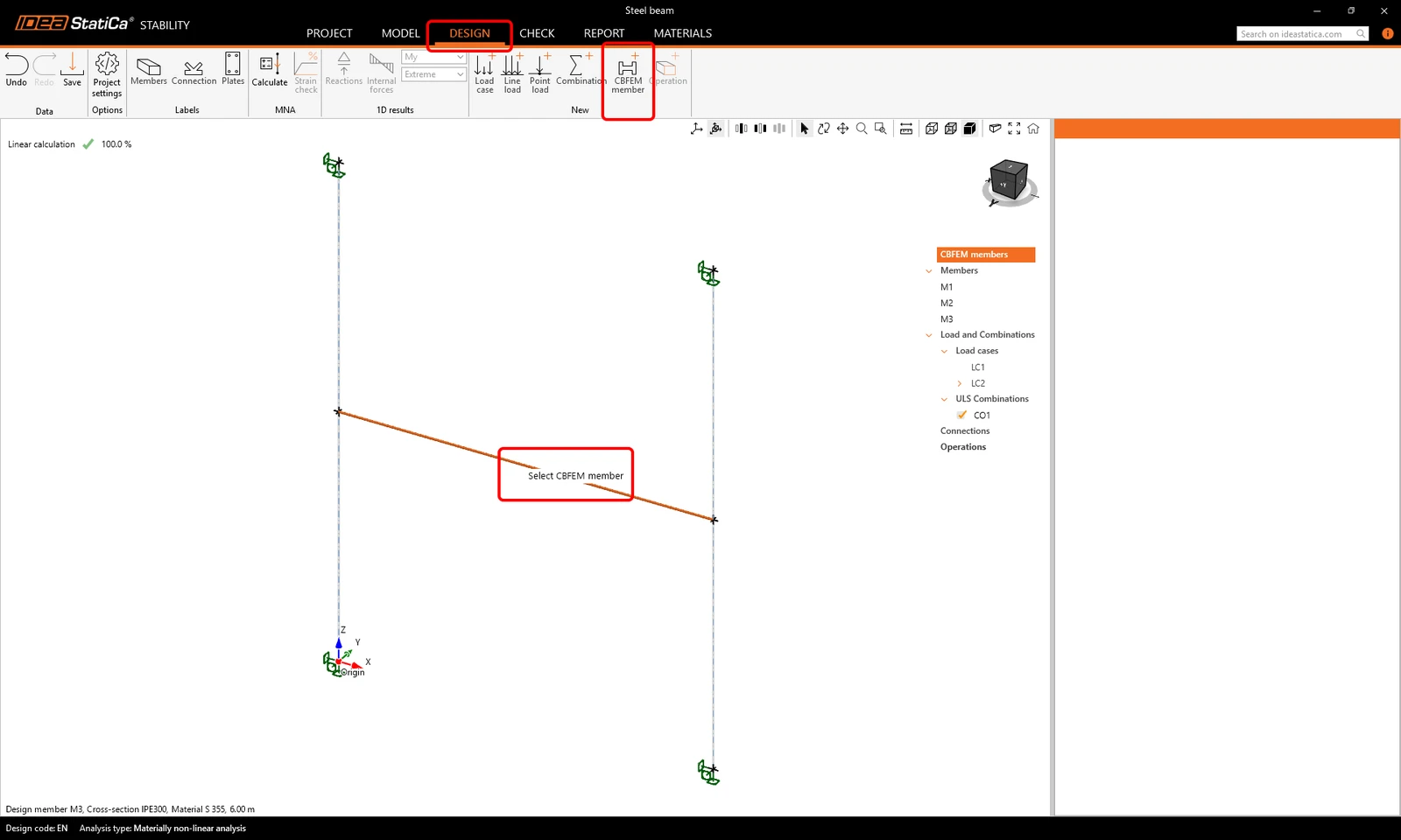
The loads are automatically taken from the Model tab. You can edit the loads in the Design tab and set the effective width and eccentricities on the CBFEM members. In this tutorial, keep the original settings.
- Read more about CBFEM members in How to define CBFEM members in Stability.
In the tree, navigate to Connections, and right-click node IN1 and select Open (or select the cube in the 3D screen and click Open in the property tab).
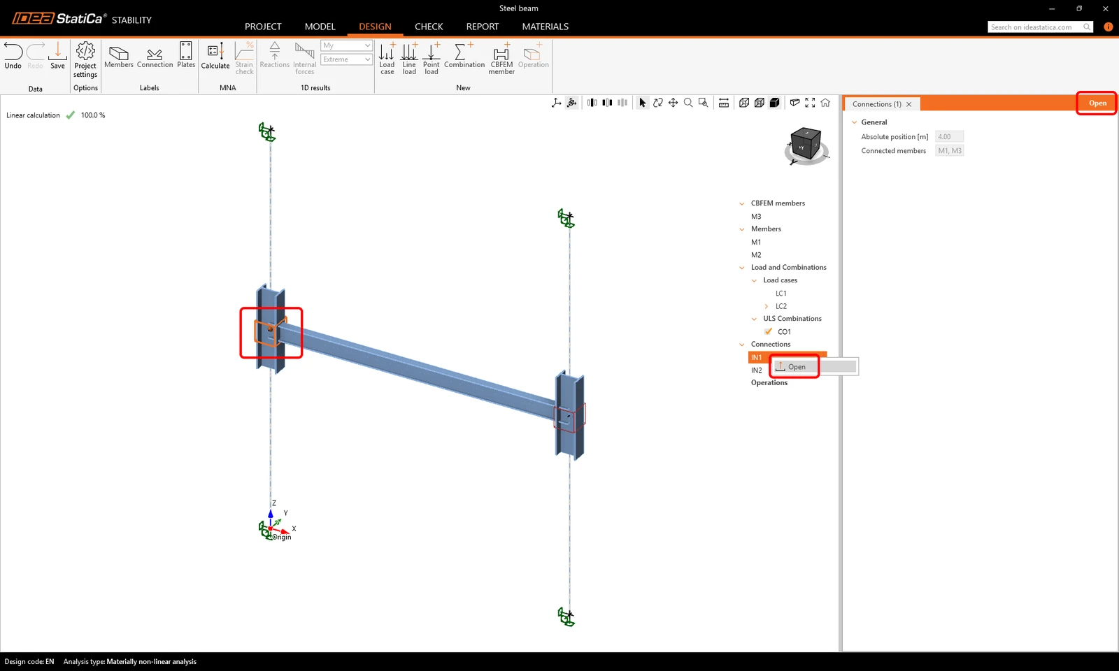
The Connection app opens, and you can design the joint and code-check it with the internal forces from the linear analysis of the substructure you previously did in the Model tab.
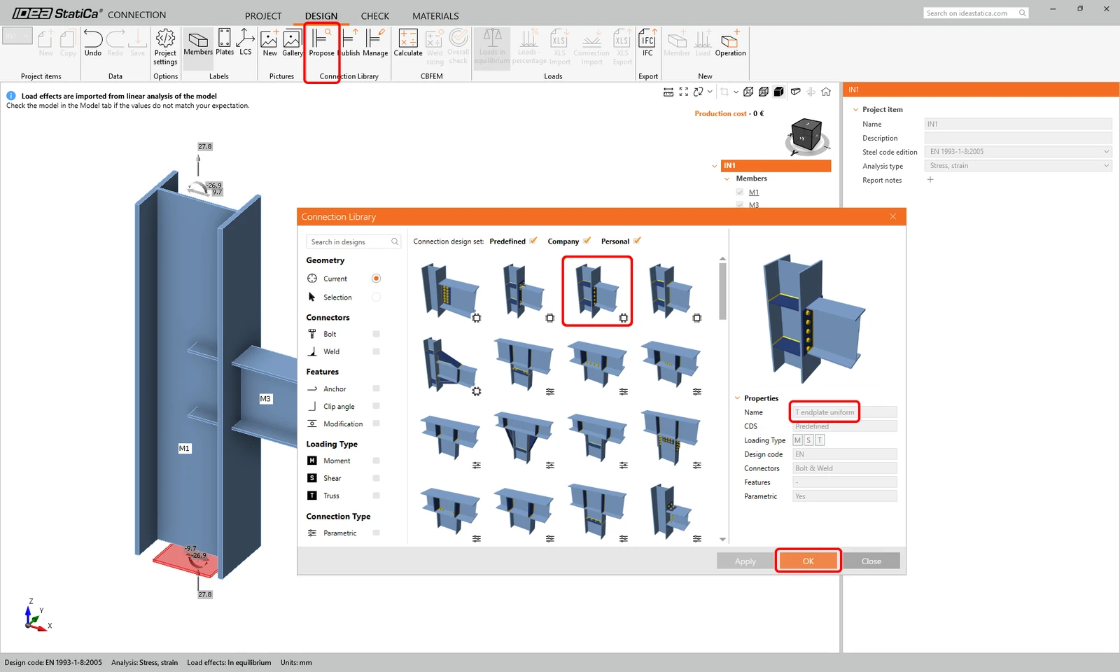
Click Propose and select the template "T endplate uniform" from the Predefined design set and click OK.
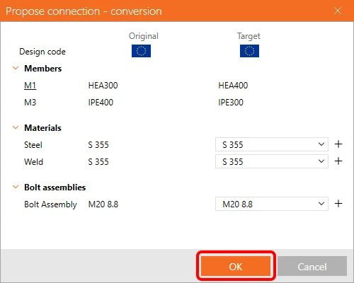
In the dialog Propose connection - conversion, just confirm the default materials with OK.
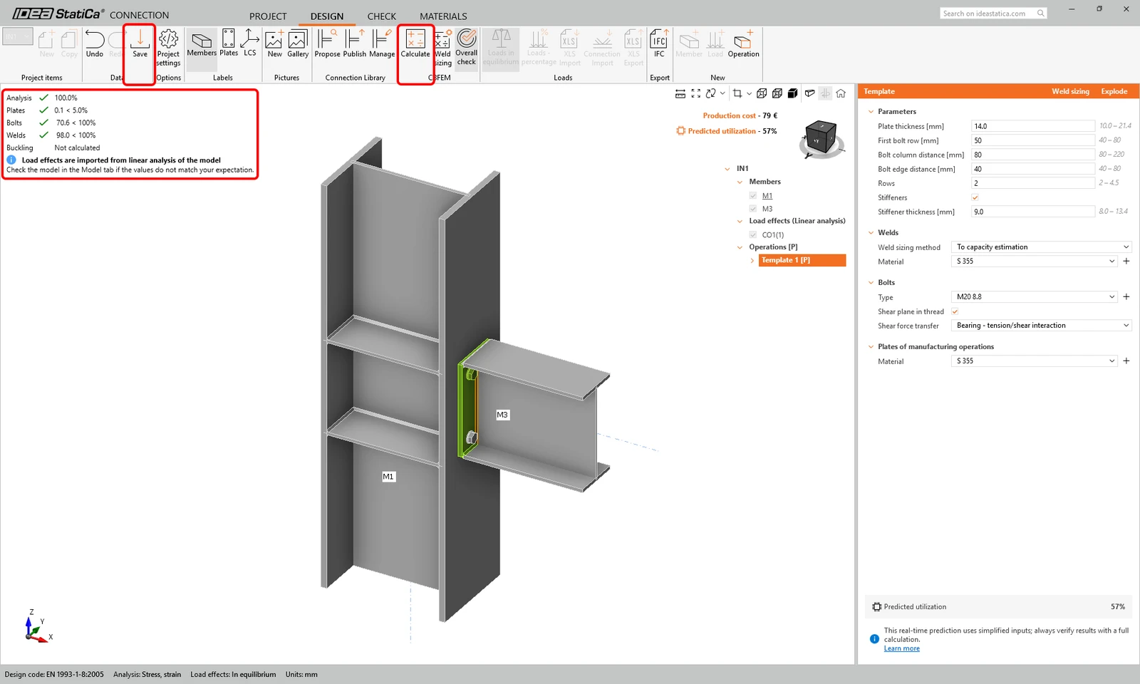
The parametric template is applied and automatically adjusts to the given member sizes, so you don't need to change the parameters now. Click Calculate to check the connection. Click Save and close the Connection app.
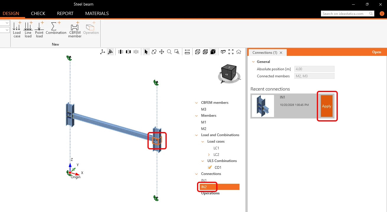
Select the connection IN2 and click Apply to reproduce the same design as for the connection IN1.
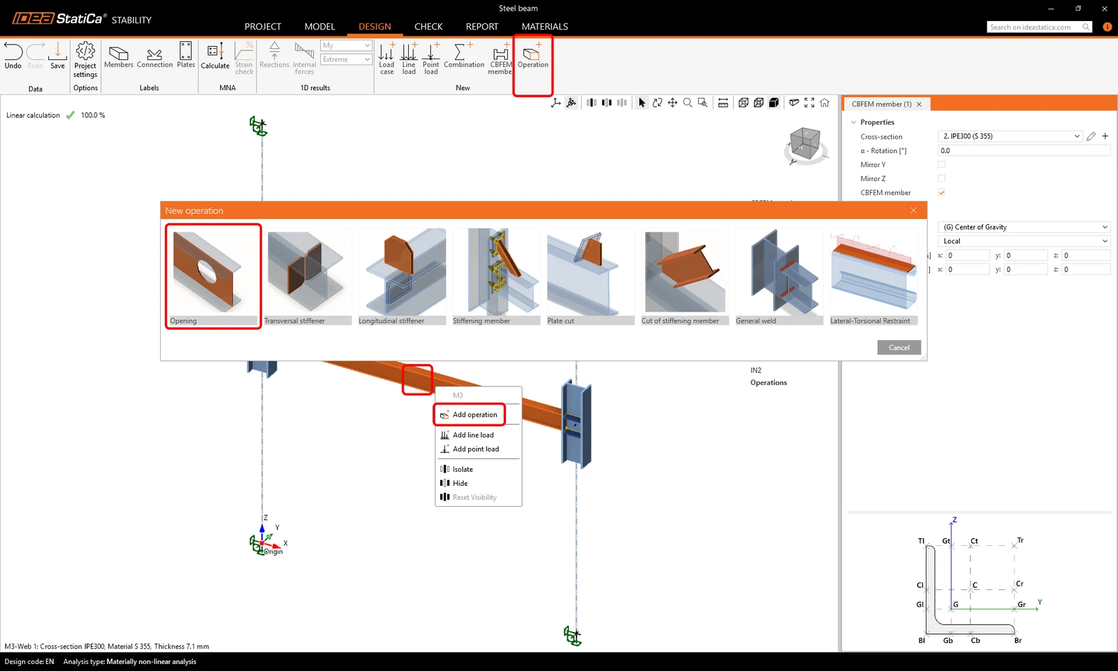
Next, you can define details of the CBFEM member, such as adding the openings to the beam web. Select the beam M3 in the 3D scene, and in the right-click context menu, select Add operation (or click on the beam M3 and click Operation in the ribbon). Choose the Opening operation.
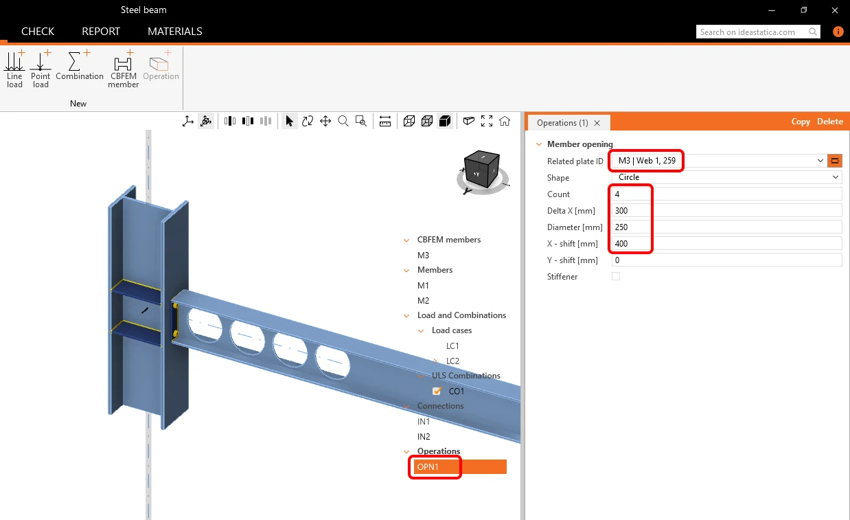
For the opening operation OPN1, change the parameters Related plate 1D to M3 | Web 1, 259, then Count to 4, Delta X [mm] to 300, Diameter [mm] to 250, and X - shift [m] to 400.
- Read more about designing steel joints in the Stability app in Design of connections in Stability.
Check
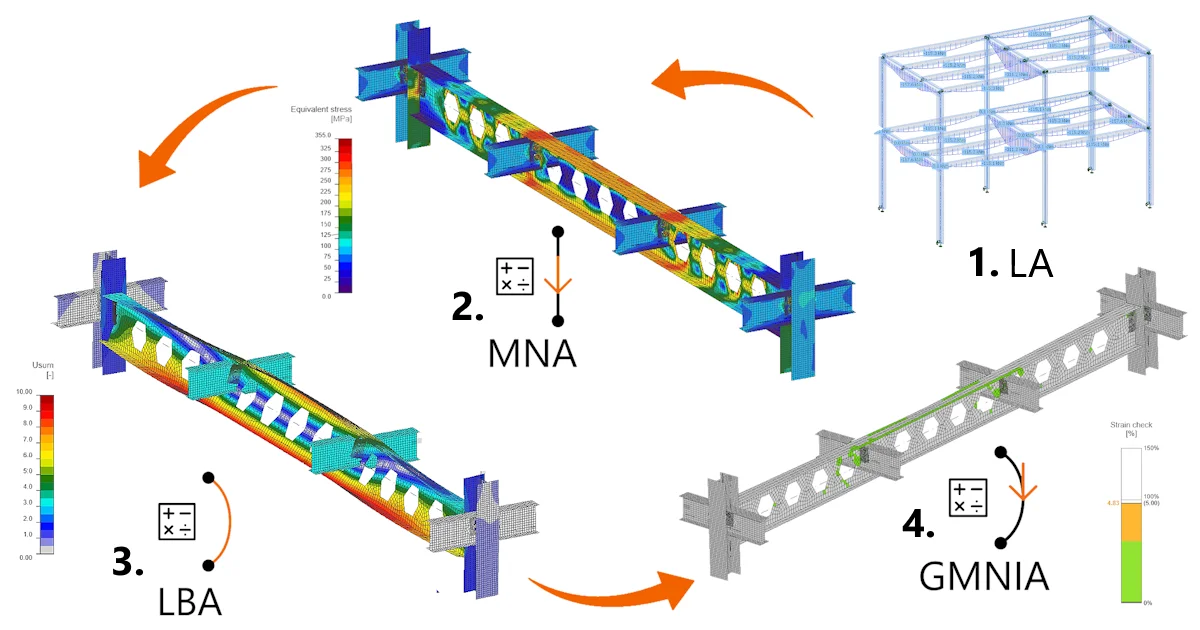
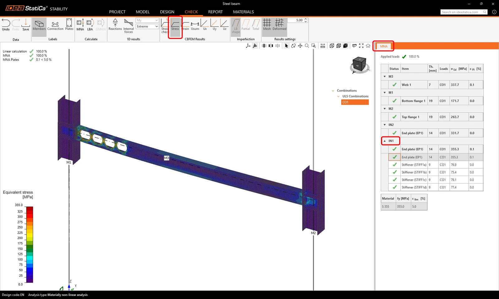
Go to the tab Check. Here you can perform three types of analyses in three steps - MNA, LBA, and GMNIA. First, calculate the MNA (materially nonlinear analysis) by clicking the ribbon icon.
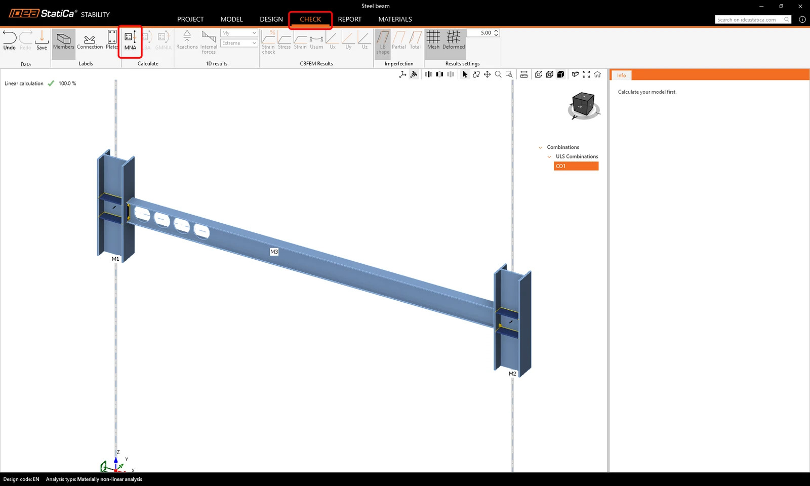
You can review the FEM analysis results, such as stress, internal forces, or deformations, considering the precise boundary conditions (connection stiffness, openings, etc.) and the code check of the steel plates for plastic strain. Click Stress to review the Equivalent stress over the substructure, and click on the IN1 in the results tab to see stress values in the connection plates.
Next, click LBA (linear buckling analysis) on the ribbon to start the calculation. Review the buckling shapes of the beam by selecting rows 1 to 6 in the tab Member imperfections. The tab displays the buckling Factor values and the Relevance [%] values to help you determine the most dangerous buckling shape of the analyzed member(s).
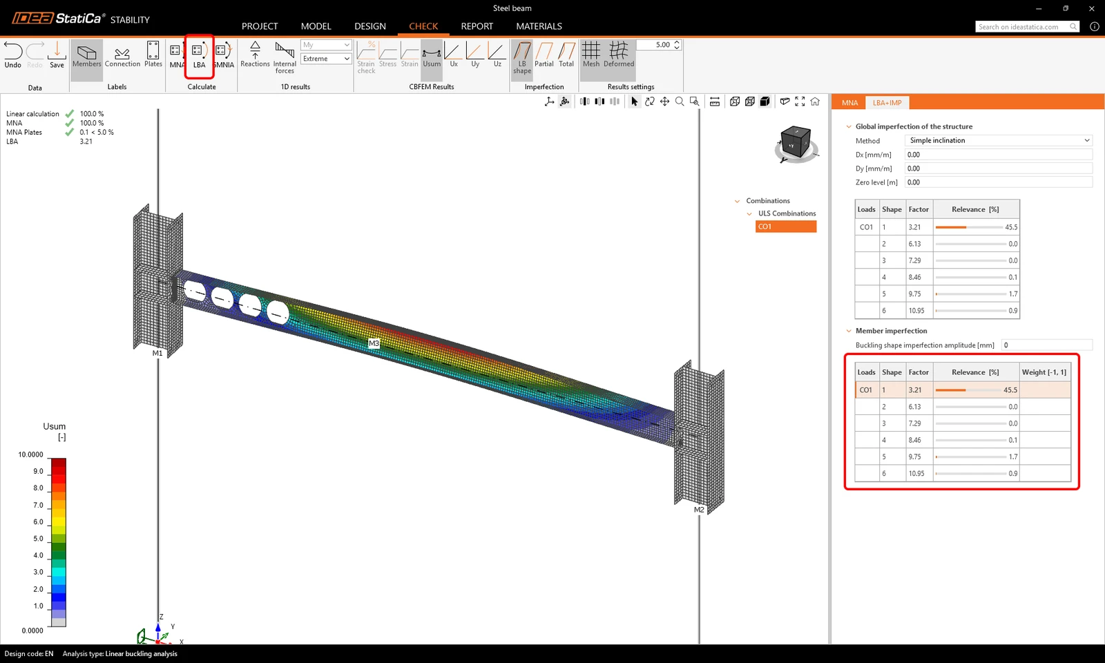
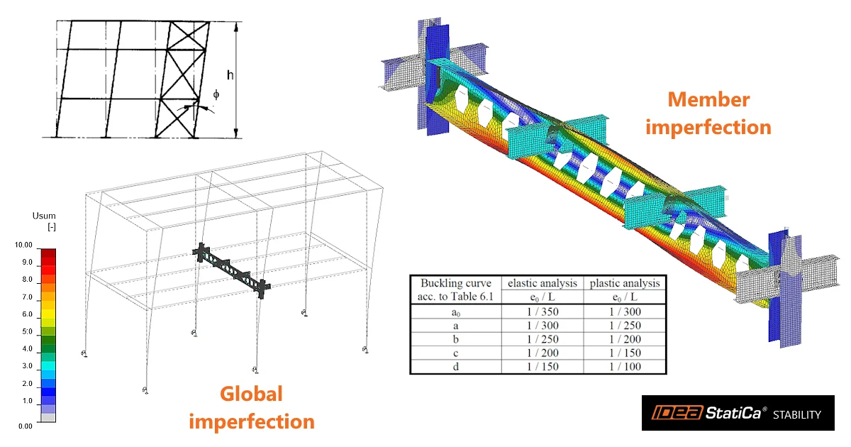
Before you run the GMNA analysis, you need to input the imperfections. Under the Member imperfections, enter the value of Buckling shape imperfections amplitude [mm] as 24.
(e0 = L/250 = (6000/250 = 24 mm; L = length of the beam - column cross-section heigth)
In the tab of buckling shapes, input 1 for the Weight [-1;1] of Shape 1. Since the model is symmetrical, you don't need to investigate the other position of the imperfection amplitude with the Weight of -1.
Then click GMNA (geometrically and materially nonlinear analysis with imperfections) to run the analysis.

- Read more about imperfections in How to input imperfections in Stability.
You can again browse all results. Click Stress and raise the deformation scale to 50 to get the full picture of the member behavior. The results tab shows that the beam meets the required design code criteria for plastic strain and is safe against the risk of loss of stability.

- Read more about MNA, LBA. and GMNIA in Types of analysis in Stability.
Report
Once the design and code checks are complete, you can print your report from the Report tab. The report is customizable. For example, you can also add the Connections report. Once set, click the Refresh button to regenerate the report.
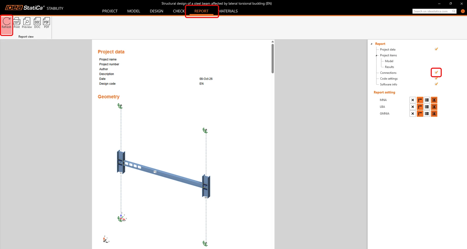
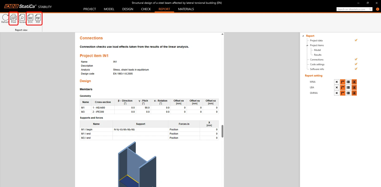
The report is generated, and you can save it in PDF or DOC (Microsoft Word) format, or Print it right away. Don't forget to save your project, and you are done!
You can continue learning IDEA StatiCa with more tutorials in the Support Center.
Want to improve your skills? Visit our Campus
Learn how to use IDEA StatiCa effectively with our self-paced e-learning courses
Start learning